8-20
MPC8240 Integrated Processor User’s Manual
DMA Register Descriptions
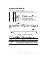
Figure 8-6 shows the bits in the CDARs.
Figure 8-6. Current Descriptor Address Register (CDAR)
Table 8-4 describes the bit settings for the CDARs.
8.7.4 Source Address Registers (SARs)
The SARs indicate the address from which the DMA controller reads data. This address can
be either a PCI memory or local memory address. The software has to ensure that this is a
valid memory address. In agent mode, all DMA to PCI read transactions are translated if
the SAR address is within the outbound translation window. See Section 3.3.2, “Outbound
PCI Address Translation,” for more information.
Table 8-5. CDAR Field Descriptions—Offsets 0x108, 0x208
Bits
Name
Reset
Value
R/W
Description
31–5
CDA
All 0s
RW
Current descriptor address. Contains the current descriptor address of the buffer
descriptor in memory. It must be aligned on an 8-word boundary. These bits are
valid only for chaining mode.
4
SNEN
0
RW
Snoop enable. When set, enables snooping of the local processor during DMA
transactions. The transaction can be a descriptor fetch or local memory read/write.
This bit is valid for both chaining and direct modes. In chaining mode, each
descriptor has individually controlled snooping characteristics.
0 Disables snooping
1 Enables processor core snooping for DMA transactions if
PICR[NO_SNOOP_EN] = 0. If PICR[NO_SNOOP_EN] = 1, snooping is
disabled.
3
EOSIE
0
RW
End-of-segment interrupt enable. Interrupt mechanism used depends on the
setting of DMR[IRQS]. This bit is valid only for chaining mode.
0 End-of-segment interrupt disabled
1 Generates an interrupt if the DMA transfer for the current descriptor is finished.
2–1
CTT
00
RW
Channel transfer type. These two bits specify the type/direction of the DMA
transfer. These bits are valid for both chaining and direct modes.
00 Local memory to local memory transfer
01 Local memory to PCI transfer
10 PCI to local memory transfer
11 PCI to PCI transfer
0
—
0
R
Reserved
CDA
CTT 0
31
5
4
3
2
1
0
Reserved
SNEN
EOSIE
Содержание MPC8240
Страница 1: ...MPC8240UM D Rev 1 1 2001 MPC8240 Integrated Processor User s Manual ...
Страница 38: ...xviii MPC8240 Integrated Processor User s Manual TABLES Table Number Title Page Number ...
Страница 48: ...xlviii MPC8240 Integrated Processor User s Manual Acronyms and Abbreviations ...
Страница 312: ...6 94 MPC8240 Integrated Processor User s Manual ROM Flash Interface Operation ...
Страница 348: ...7 36 MPC8240 Integrated Processor User s Manual PCI Host and Agent Modes ...
Страница 372: ...8 24 MPC8240 Integrated Processor User s Manual DMA Register Descriptions ...
Страница 394: ...9 22 MPC8240 Integrated Processor User s Manual I2O Interface ...
Страница 412: ...10 18 MPC8240 Integrated Processor User s Manual Programming Guidelines ...
Страница 454: ...12 14 MPC8240 Integrated Processor User s Manual Internal Arbitration ...
Страница 466: ...13 12 MPC8240 Integrated Processor User s Manual Exception Latencies ...
Страница 516: ...16 14 Watchpoint Trigger Applications ...
Страница 538: ...B 16 MPC8240 Integrated Processor User s Manual Setting the Endian Mode of Operation ...
Страница 546: ...C 8 MPC8240 Integrated Processor User s Manual ...
Страница 640: ...INDEX Index 16 MPC8240 Integrated Processor User s Manual ...


