


4-14
MPC8240 Integrated Processor User’s Manual
PCI Interface Configuration Registers
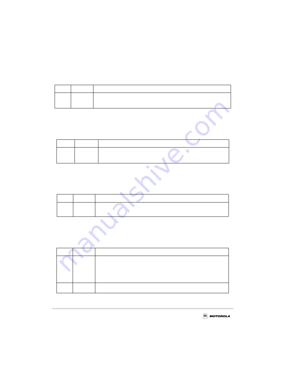
4.2.3 Programming Interface—Offset 0x09
Table 4-7 describes the PCI programming interface register (PIR).
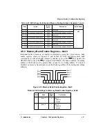
4.2.4 PCI Base Class Code—Offset 0x0B
Table 4-8 describes the PCI base class code register (PBCCR).
4.2.5 PCI Cache Line Size—Offset 0x0C
Table 4-9 describes the processor cache line size register (PCLSR).
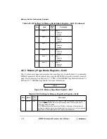
4.2.6 Latency Timer—Offset 0x0D
Table 4-10 describes the PCI latency timer register (PLTR).
Table 4-7. Programming Interface—0x09
Bits Reset
Value
Description
msb 7–0
Mode-
dependent
0x00 When MPC8240 is configured as host bridge
0x01 When MPC8240 is configured as an agent device to indicate the programming model
supports the I
2
O interface
Table 4-8. PCI Base Class Code—0x0B
Bits Reset
Value
Description
msb 7–0
Mode-
dependent
0x06 When MPC8240 is configured as a host bridge to indicate “Host Bridge.”
0x0E When MPC8240 is configured as a target device to indicate the device is an
agent and is I
2
O capable.
Table 4-9. Cache Line Size Register—0x0C
Bits Reset
Value
Description
msb 7–0
0x00
Represents the cache line size of the processor in terms of 32-bit words (eight 32-bit
words = 32 bytes). This register is read-write; however, an attempt to program this
register to any value other than 8 results in setting it to 0.
Table 4-10. Latency Timer Register—0x0D
Bits Reset
Value
Description
msb 7–3 0000_0
The maximum number of PCI clocks for which the MPC8240, which is mastering a
transaction, will hold the bus after the PCI bus grant has been negated. The entire value
in this register represents the total latency in PCI clocks. Thus the total latency is the
value in bits 7–3 multiplied by 8 (because bits 2–0 are read-only as zeros). Refer to the
PCI 2.1 specification for the rules by which the PCI bus interface unit completes
transactions when the timer has expired.
2–0
000
Read-only bits—Because these bits are read-only as zeros, the granularity of the latency
timer value is 8 PCI clocks.
Содержание MPC8240
Страница 1: ...MPC8240UM D Rev 1 1 2001 MPC8240 Integrated Processor User s Manual ...
Страница 38: ...xviii MPC8240 Integrated Processor User s Manual TABLES Table Number Title Page Number ...
Страница 48: ...xlviii MPC8240 Integrated Processor User s Manual Acronyms and Abbreviations ...
Страница 312: ...6 94 MPC8240 Integrated Processor User s Manual ROM Flash Interface Operation ...
Страница 348: ...7 36 MPC8240 Integrated Processor User s Manual PCI Host and Agent Modes ...
Страница 372: ...8 24 MPC8240 Integrated Processor User s Manual DMA Register Descriptions ...
Страница 394: ...9 22 MPC8240 Integrated Processor User s Manual I2O Interface ...
Страница 412: ...10 18 MPC8240 Integrated Processor User s Manual Programming Guidelines ...
Страница 454: ...12 14 MPC8240 Integrated Processor User s Manual Internal Arbitration ...
Страница 466: ...13 12 MPC8240 Integrated Processor User s Manual Exception Latencies ...
Страница 516: ...16 14 Watchpoint Trigger Applications ...
Страница 538: ...B 16 MPC8240 Integrated Processor User s Manual Setting the Endian Mode of Operation ...
Страница 546: ...C 8 MPC8240 Integrated Processor User s Manual ...
Страница 640: ...INDEX Index 16 MPC8240 Integrated Processor User s Manual ...


