Chapter 10. I
2
C Interface
10-15
Programming Guidelines
When an interrupt occurs at the end of the address cycle, the master remains in transmit
mode. If master receive mode is required, I2CCR[MTX] should be toggled at this stage. See
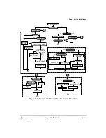
Section 10.4.8, “Interrupt Service Routine Flowchart.”
If the interrupt function is disabled, software can service the I2CDR in the main program
by monitoring I2CSR[MIF]. In this case, I2CSR[MIF] should be polled rather than
I2CSR[MCF] because MCF behaves differently when arbitration is lost. Note that interrupt
or other bus conditions may be detected by the MPC8240 before the I
2
C signals have time
to settle. Thus, when polling I2CSR[MIF] (or any other I2SCR bits), software delays may
be needed (in order to give the I
2
C signals sufficient time to settle).
During slave-mode address cycles (I2CSR[MAAS] = 1), I2CSR[SRW] should be read to
determine the direction of the subsequent transfer and I2CCR[MTX] should be
programmed accordingly. For slave-mode data cycles (I2CSR[MAAS] = 0), I2CSR[SRW]
is not valid and I2CCR[MTX] should be read to determine the direction of the current
transfer. See Section 10.4.8, “Interrupt Service Routine Flowchart,” for more details.
10.4.4 Generation of STOP
A data transfer ends with a STOP condition generated by the master device. A master
transmitter can generate a STOP condition after all the data has been transmitted.
If a master receiver wants to terminate a data transfer, it must inform the slave transmitter
by not acknowledging the last byte of data, which is done by setting the transmit
acknowledge (I2CCR[TXAK]) bit before reading the next-to-last byte of data. For one-byte
transfers, a dummy read should be performed by the interrupt service routine. (See
Section 10.4.8, “Interrupt Service Routine Flowchart.”) Before the interrupt service routine
reads the last byte of data, a STOP condition must first be generated by the MPC8240.
The MPC8240 automatically generates a STOP if I2CCR[TXAK] = 1. Therefore,
I2CCR[TXAK] must be set to a 1 before allowing the MPC8240 to receive the last data byte
on the I
2
C bus.
10.4.5 Generation of Repeated START
At the end of a data transfer, if the master still wants to communicate on the bus, it can
generate another START condition followed by another slave address without first
generating a STOP condition by setting I2CCR[RSTA].
10.4.6 Generation of SCK when SDA Low
In some cases it is necessary to force the MPC8240 to become the I
2
C bus master out of
reset and drive the SCK signal (even though SDA may already be driven indicating that the
bus is busy). This can occur when a system reset does not cause all I
2
C devices to be reset.
Thus, the SDA signal can be driven low by another I
2
C device while the MPC8240 is
coming out of reset and will stay low indefinitely. In order to force the MPC8240 to
Содержание MPC8240
Страница 1: ...MPC8240UM D Rev 1 1 2001 MPC8240 Integrated Processor User s Manual ...
Страница 38: ...xviii MPC8240 Integrated Processor User s Manual TABLES Table Number Title Page Number ...
Страница 48: ...xlviii MPC8240 Integrated Processor User s Manual Acronyms and Abbreviations ...
Страница 312: ...6 94 MPC8240 Integrated Processor User s Manual ROM Flash Interface Operation ...
Страница 348: ...7 36 MPC8240 Integrated Processor User s Manual PCI Host and Agent Modes ...
Страница 372: ...8 24 MPC8240 Integrated Processor User s Manual DMA Register Descriptions ...
Страница 394: ...9 22 MPC8240 Integrated Processor User s Manual I2O Interface ...
Страница 412: ...10 18 MPC8240 Integrated Processor User s Manual Programming Guidelines ...
Страница 454: ...12 14 MPC8240 Integrated Processor User s Manual Internal Arbitration ...
Страница 466: ...13 12 MPC8240 Integrated Processor User s Manual Exception Latencies ...
Страница 516: ...16 14 Watchpoint Trigger Applications ...
Страница 538: ...B 16 MPC8240 Integrated Processor User s Manual Setting the Endian Mode of Operation ...
Страница 546: ...C 8 MPC8240 Integrated Processor User s Manual ...
Страница 640: ...INDEX Index 16 MPC8240 Integrated Processor User s Manual ...


