7-8
MPC8240 Integrated Processor User’s Manual
PCI Bus Protocol
7.2.4 Power-Saving Modes and the PCI Arbiter
In the sleep power-saving mode, the clock signal driving PCI_SYNC_IN can be disabled.
If the clock is disabled, the arbitration logic is not able to perform its function. System
programmers must park the bus with a device that can sustain the AD[31:0], C/BE[3:0] and
PAR signals prior to disabling the PCI_SYNC_IN signal. If the bus is parked on the
MPC8240 when its clocks are stopped, then the MPC8240 sustains the AD[31:0],
C/BE[3:0] and PAR signals in their prior states. In this situation, the only way for another
agent to use the PCI bus is by waking the MPC8240. In nap and doze power-saving modes,
the arbiter continues to operate allowing other PCI devices to run transactions.
7.2.5 Broken Master Lock-Out
The PCI bus arbiter on the MPC8240 has a feature that allows it to lock out any masters
that are broken or ill-behaved. The broken master feature is controlled by programming bit
12 of the PCI arbitration control register (0b0 = enabled, 0b1 = disabled).
When the broken master feature is enabled, a granted device that does not assert FRAME
within 16 PCI clock cycles after the bus is idle will have its grant removed and subsequent
requests will be ignored until its REQ is negated for at least one clock cycle. This prevents
ill-behaved masters from monopolizing the bus. When the broken master feature is
disabled, a device that requests the bus and receives a grant never loses its grant until and
unless it begins a transaction or negates its REQ signal. Disabling the broken master feature
is not recommended.
7.3 PCI Bus Protocol
This section provides a general description of the PCI bus protocol. Specific PCI bus
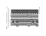
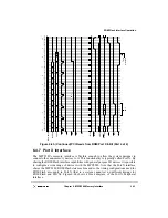
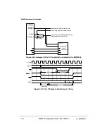
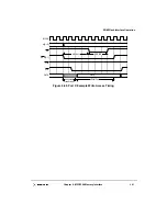
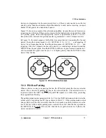
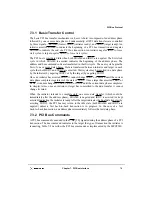
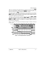
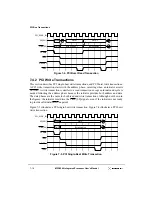
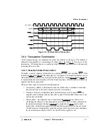
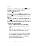
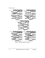
transactions are described in Section 7.4, “PCI Bus Transactions.” Refer to Figure 7-3,
Figure 7-4, Figure 7-5, and Figure 7-6 for examples of the transfer-control mechanisms
described in this section.
All signals are sampled on the rising edge of the PCI bus clock (PCI_SYNC_IN). Each
signal has a setup and hold aperture with respect to the rising clock edge in which
transitions are not allowed. Outside this aperture, signal values or transitions have no
significance. See the
MPC8240 Hardware Specification
for specific setup and hold times.
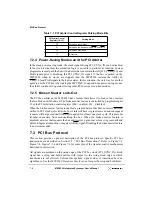
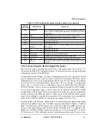
Table 7-1. PCI Arbiter Control Register Parking Mode Bits
PCI Arbiter Control
Register [14–13]
Parking Mode
00
Parked on last master
01
Parked on the device using REQ0 and GNT0
10
Parked on MPC8240
11
Reserved
Содержание MPC8240
Страница 1: ...MPC8240UM D Rev 1 1 2001 MPC8240 Integrated Processor User s Manual ...
Страница 38: ...xviii MPC8240 Integrated Processor User s Manual TABLES Table Number Title Page Number ...
Страница 48: ...xlviii MPC8240 Integrated Processor User s Manual Acronyms and Abbreviations ...
Страница 312: ...6 94 MPC8240 Integrated Processor User s Manual ROM Flash Interface Operation ...
Страница 348: ...7 36 MPC8240 Integrated Processor User s Manual PCI Host and Agent Modes ...
Страница 372: ...8 24 MPC8240 Integrated Processor User s Manual DMA Register Descriptions ...
Страница 394: ...9 22 MPC8240 Integrated Processor User s Manual I2O Interface ...
Страница 412: ...10 18 MPC8240 Integrated Processor User s Manual Programming Guidelines ...
Страница 454: ...12 14 MPC8240 Integrated Processor User s Manual Internal Arbitration ...
Страница 466: ...13 12 MPC8240 Integrated Processor User s Manual Exception Latencies ...
Страница 516: ...16 14 Watchpoint Trigger Applications ...
Страница 538: ...B 16 MPC8240 Integrated Processor User s Manual Setting the Endian Mode of Operation ...
Страница 546: ...C 8 MPC8240 Integrated Processor User s Manual ...
Страница 640: ...INDEX Index 16 MPC8240 Integrated Processor User s Manual ...

