Chapter 7. PCI Bus Interface
7-21
PCI Bus Transactions
7.4.4 Fast Back-to-Back Transactions
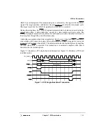
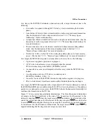
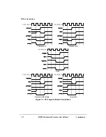
The PCI bus allows fast back-to-back transactions by the same master. During a fast
back-to-back transaction, the initiator starts the next transaction immediately without an
idle state. The last data phase completes when FRAME is negated, and IRDY and TRDY
are asserted. The current master starts another transaction in the clock cycle immediately
following the last data transfer for the previous transaction.
Fast back-to-back transactions must avoid contention on the TRDY, DEVSEL, PERR, and
STOP signals. There are two types of fast back-to-back transactions—those that access the
same target, and those that access multiple targets sequentially. The first type places the
burden of avoiding contention on the initiator; the second type places the burden of
avoiding contention on all potential targets.
As an initiator, the MPC8240 does not perform any fast back-to-back transactions. As a
target, the MPC8240 supports both types of fast back-to-back transactions.
During fast back-to-back transactions, the MPC8240 monitors the bus states to determine
if it is the target of a transaction. If the previous transaction was not directed to the
MPC8240 and the current transaction is directed at the MPC8240, the MPC8240 delays the
assertion of DEVSEL (as well as TRDY, STOP, and PERR) for one clock cycle to allow the
other target to stop driving the bus.
7.4.5 Configuration Cycles
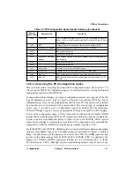
This section describes PCI configuration cycles used for configuring standard PCI devices.
The PCI configuration space of any device is intended for configuration, initialization, and
catastrophic error-handling functions only. Access to the PCI configuration space should be
limited to initialization and error-handling software.
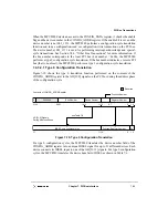
7.4.5.1 The PCI Configuration Space Header
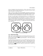
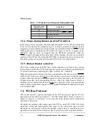
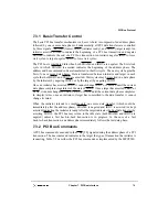
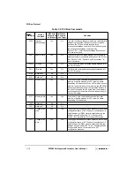
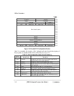
The first 64 bytes of the 256-byte configuration space consists of a predefined header that
every PCI device must support. The predefined header is shown in Figure 7-8. The rest of
the 256-byte configuration space is device-specific.
The first 16 bytes of the predefined header are defined the same for all PCI devices; the
remaining 48 bytes of the header may have differing layouts depending on the function of
the device. Most PCI devices use the configuration header layout shown in Figure 7-8.
Содержание MPC8240
Страница 1: ...MPC8240UM D Rev 1 1 2001 MPC8240 Integrated Processor User s Manual ...
Страница 38: ...xviii MPC8240 Integrated Processor User s Manual TABLES Table Number Title Page Number ...
Страница 48: ...xlviii MPC8240 Integrated Processor User s Manual Acronyms and Abbreviations ...
Страница 312: ...6 94 MPC8240 Integrated Processor User s Manual ROM Flash Interface Operation ...
Страница 348: ...7 36 MPC8240 Integrated Processor User s Manual PCI Host and Agent Modes ...
Страница 372: ...8 24 MPC8240 Integrated Processor User s Manual DMA Register Descriptions ...
Страница 394: ...9 22 MPC8240 Integrated Processor User s Manual I2O Interface ...
Страница 412: ...10 18 MPC8240 Integrated Processor User s Manual Programming Guidelines ...
Страница 454: ...12 14 MPC8240 Integrated Processor User s Manual Internal Arbitration ...
Страница 466: ...13 12 MPC8240 Integrated Processor User s Manual Exception Latencies ...
Страница 516: ...16 14 Watchpoint Trigger Applications ...
Страница 538: ...B 16 MPC8240 Integrated Processor User s Manual Setting the Endian Mode of Operation ...
Страница 546: ...C 8 MPC8240 Integrated Processor User s Manual ...
Страница 640: ...INDEX Index 16 MPC8240 Integrated Processor User s Manual ...

