
Chapter 2. Signal Descriptions and Clocking
2-25
Detailed Signal Descriptions
2.2.4 I
2
C Interface Control Signals
These two signals serve as a communication interconnect with other devices. All devices
connected to these two signals must have open-drain or open-collector outputs. The logic
AND function is performed on both of these signals with external pull-up resistors. Refer
to the MPC8240 Hardware Specification for the electrical characteristics of these signals.
C Interface,” has a complete description of the I
2
C protocol and the relative
timings of the I
2
C signals.
2.2.4.1 Serial Data (SDA)
This signal is an input when the MPC8240 is in a receiving mode and an output when it is
transmitting (as an I
2
C master or a slave).
2.2.4.1.1 Serial Data (SDA)—Output
Following is the state meaning of the SDA output signal when the MPC8240 is transmitting
(as an I
2
C master or a slave).
State Meaning
Asserted/Negated—Used to drive the data.
2.2.4.1.2 Serial Data (SDA)—Input
Following is the state meaning of the SDA input signal when the MPC8240 is receiving
data.
State Meaning
Asserted/Negated—Used to receive data from other devices. The bus
is assumed to be busy when SDA is detected low.
2.2.4.2 Serial Clock (SCL)
This signal is an input when the MPC8240 is programmed as an I
2
C slave and an output
when programmed as an I
2
C master.
2.2.4.2.1 Serial Clock (SCL)—Output
Following is the state meaning of the SCL output signal when the MPC8240 is an I
2
C
master.
State Meaning
Asserted/Negated—Driven along with SDA as the clock for the data.
2.2.4.2.2 Serial Clock (SCL)—Input
Following is the state meaning of the SCL output signal when the MPC8240 is an I
2
C slave.
State Meaning
Asserted/Negated—The I
2
C unit uses this signal to synchronize
incoming data on SDA. The bus is assumed to be busy when this
signal is detected low.
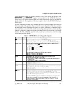
2.2.5 System Control and Power Management Signals
The following sections describe the system control and power management signals of the
MPC8240.
Содержание MPC8240
Страница 1: ...MPC8240UM D Rev 1 1 2001 MPC8240 Integrated Processor User s Manual ...
Страница 38: ...xviii MPC8240 Integrated Processor User s Manual TABLES Table Number Title Page Number ...
Страница 48: ...xlviii MPC8240 Integrated Processor User s Manual Acronyms and Abbreviations ...
Страница 312: ...6 94 MPC8240 Integrated Processor User s Manual ROM Flash Interface Operation ...
Страница 348: ...7 36 MPC8240 Integrated Processor User s Manual PCI Host and Agent Modes ...
Страница 372: ...8 24 MPC8240 Integrated Processor User s Manual DMA Register Descriptions ...
Страница 394: ...9 22 MPC8240 Integrated Processor User s Manual I2O Interface ...
Страница 412: ...10 18 MPC8240 Integrated Processor User s Manual Programming Guidelines ...
Страница 454: ...12 14 MPC8240 Integrated Processor User s Manual Internal Arbitration ...
Страница 466: ...13 12 MPC8240 Integrated Processor User s Manual Exception Latencies ...
Страница 516: ...16 14 Watchpoint Trigger Applications ...
Страница 538: ...B 16 MPC8240 Integrated Processor User s Manual Setting the Endian Mode of Operation ...
Страница 546: ...C 8 MPC8240 Integrated Processor User s Manual ...
Страница 640: ...INDEX Index 16 MPC8240 Integrated Processor User s Manual ...


