Chapter 9. Message Unit (with I
2
O)
9-13
I
2
O Interface
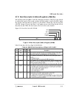
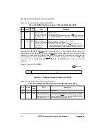
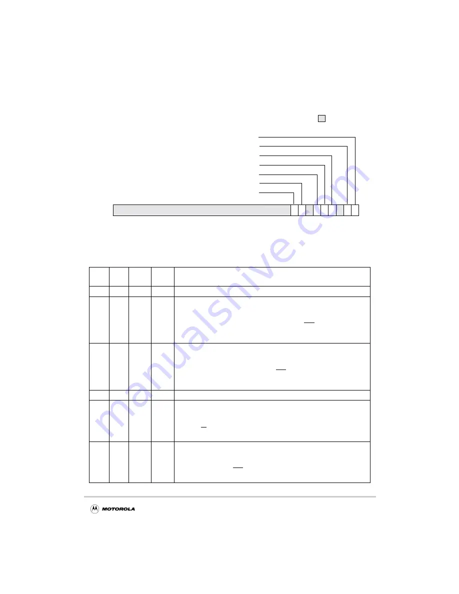
Figure 9-9 shows the bits of the IMISR.
Figure 9-9. Inbound Message Interrupt Status Register (IMISR)
Table 9-13 shows the bit settings for the IMISR.
Table 9-13. IMISR Field Descriptions—Offset 0x0_0100
Bits
Name
Reset
Value
R/W
Description
31–11
—
All 0s
R
Reserved
8
OFO
0
Read
Write 1
clears
this bit
Outbound free_list overflow condition
0 No overflow condition
1 Indicates that the outbound free_list FIFO head pointer is equal to the
outbound free_list FIFO tail pointer and the queue is full. A machine check is
signalled to the processor core through the internal mcp signal and a machine
check exception is taken (if enabled). See Chapter 13, “Error Handling.” This
bit is set only if the OFOM mask bit in IMIMR is cleared.
7
IPO
0
Read
Write 1
clears
this bit
Inbound post_list overflow condition
0 No overflow condition
1 Indicates that the inbound free_list FIFO head pointer is equal to the inbound
free_list FIFO tail pointer and the queue is full. A machine check is signalled to
the processor core through the internal mcp signal and a machine check
exception is taken (if enabled). This bit is set only if the IPOM mask bit in
IMIMR is cleared.
6
—
0
R
Reserved
5
IPQI
0
Read
Write 1
clears
this bit
Inbound post queue interrupt (I
2
O interface)
0 No MFA in the IFQPR
1 Indicates that the PCI master has posted an MFA to the inbound post_list FIFO
through the IFQPR. Interrupt is signalled to the processor core through the
internal int signal. This bit is set only if the inbound post queue interrupt mask
(IMIMR[IPQIM]) bit is cleared.
4
DMC
0
R
Doorbell register machine check condition
0 No doorbell register machine check condition.This bit is cleared when
IDBR[MC] is cleared.
1 Indicates that a remote processor has generated a machine check condition
(causing assertion of mcp) by setting IDBR[MC]. Note that this bit is set only if
the mask bit, IMIMR[DMCM] = 0.
0 0 0 0_0 0 0 0_0 0 0 0_0 0 0 0_0 0 0 0_0 0 0
0
0
31
9
8
7
6
5
4
3
2
1
0
Reserved
OFOI
IPOI
IPQI
MCI
IDI
IM1I
IM0I
Содержание MPC8240
Страница 1: ...MPC8240UM D Rev 1 1 2001 MPC8240 Integrated Processor User s Manual ...
Страница 38: ...xviii MPC8240 Integrated Processor User s Manual TABLES Table Number Title Page Number ...
Страница 48: ...xlviii MPC8240 Integrated Processor User s Manual Acronyms and Abbreviations ...
Страница 312: ...6 94 MPC8240 Integrated Processor User s Manual ROM Flash Interface Operation ...
Страница 348: ...7 36 MPC8240 Integrated Processor User s Manual PCI Host and Agent Modes ...
Страница 372: ...8 24 MPC8240 Integrated Processor User s Manual DMA Register Descriptions ...
Страница 394: ...9 22 MPC8240 Integrated Processor User s Manual I2O Interface ...
Страница 412: ...10 18 MPC8240 Integrated Processor User s Manual Programming Guidelines ...
Страница 454: ...12 14 MPC8240 Integrated Processor User s Manual Internal Arbitration ...
Страница 466: ...13 12 MPC8240 Integrated Processor User s Manual Exception Latencies ...
Страница 516: ...16 14 Watchpoint Trigger Applications ...
Страница 538: ...B 16 MPC8240 Integrated Processor User s Manual Setting the Endian Mode of Operation ...
Страница 546: ...C 8 MPC8240 Integrated Processor User s Manual ...
Страница 640: ...INDEX Index 16 MPC8240 Integrated Processor User s Manual ...

