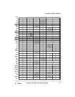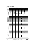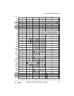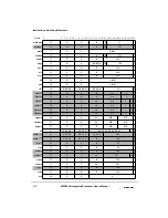
Appendix B. Bit and Byte Ordering
B-15
Setting the Endian Mode of Operation
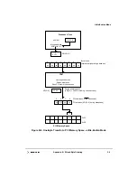
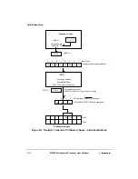
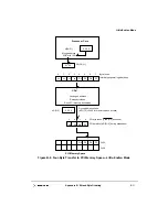
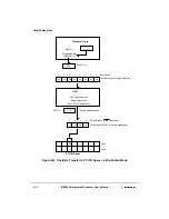
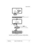
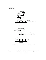
B.4.1 I/O Addressing in Little-Endian Mode
For a system running in big-endian mode, both the processor core and the memory
subsystem recognize the same byte as byte 0. However, this is not true for a system running
in little-endian mode because of the munged address bits when the MPC8240 accesses
external memory.
For I/O transfers in little-endian mode to transfer bytes properly, they must be performed
as if the bytes transferred were accessed one at a time using the little-endian address
modification appropriate for the single-byte transfers (that is, the lowest order address bits
must be XORed with 0b111). This does not mean that I/O operations in little-endian
systems must be performed using only one-byte-wide transfers. Data transfers can be as
wide as desired, but the order of the bytes within double words must be as if they were
fetched or stored one at a time. That is, for a true little-endian I/O device, the system must
provide a way to munge and unmunge the addresses and reverse the bytes within a double
word (MSB to LSB).
A load or store that maps to a control register on an external device may require the bytes
of the register data to be reversed. If this reversal is required, the load and store with
byte-reverse instructions (lhbrx, lwbrx, sthbrx, and stwbrx) may be used.
B.5 Setting the Endian Mode of Operation
The MPC8240 powers up in big-endian mode. The endian mode should be set early in the
initialization routine and remain unchanged for the duration of system operation. To switch
between the different endian modes of operation, the processor core must run in serialized
mode and the caches must be disabled. Switching back and forth between endian modes is
not recommended.
To switch the system from big-endian to little-endian mode, the LE and ILE bits in the
processor core’s MSR should be set using an mtmsr instruction that resides on an odd word
boundary (A[29] = 1). The instruction that is executed next is fetched from this address plus
8. (If the mtmsr instruction resides on an even word boundary (A[29] = 0), then the
instruction would be executed twice due to the address munging of little-endian mode.)
After the processor core has been programmed for little-endian mode, the
PICR1[LE_MODE] parameter in the peripheral control logic is set.
To switch the system from little- to big-endian mode, the LE and ILE bits in the processor
core’s MSR are cleared using an mtmsr instruction that resides on an even word boundary
(A[29] = 0). The instruction that is executed next is fetched from this address plus 12. After
the processor core is programmed for big-endian mode, the PICR1[LE_MODE] parameter
in the peripheral control logic is cleared.
Содержание MPC8240
Страница 1: ...MPC8240UM D Rev 1 1 2001 MPC8240 Integrated Processor User s Manual ...
Страница 38: ...xviii MPC8240 Integrated Processor User s Manual TABLES Table Number Title Page Number ...
Страница 48: ...xlviii MPC8240 Integrated Processor User s Manual Acronyms and Abbreviations ...
Страница 312: ...6 94 MPC8240 Integrated Processor User s Manual ROM Flash Interface Operation ...
Страница 348: ...7 36 MPC8240 Integrated Processor User s Manual PCI Host and Agent Modes ...
Страница 372: ...8 24 MPC8240 Integrated Processor User s Manual DMA Register Descriptions ...
Страница 394: ...9 22 MPC8240 Integrated Processor User s Manual I2O Interface ...
Страница 412: ...10 18 MPC8240 Integrated Processor User s Manual Programming Guidelines ...
Страница 454: ...12 14 MPC8240 Integrated Processor User s Manual Internal Arbitration ...
Страница 466: ...13 12 MPC8240 Integrated Processor User s Manual Exception Latencies ...
Страница 516: ...16 14 Watchpoint Trigger Applications ...
Страница 538: ...B 16 MPC8240 Integrated Processor User s Manual Setting the Endian Mode of Operation ...
Страница 546: ...C 8 MPC8240 Integrated Processor User s Manual ...
Страница 640: ...INDEX Index 16 MPC8240 Integrated Processor User s Manual ...

