Chapter 2. Signal Descriptions and Clocking
2-23
Detailed Signal Descriptions
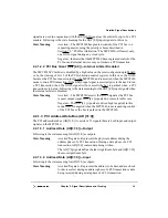
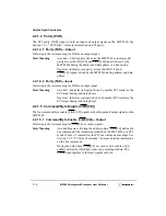
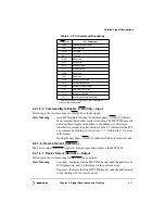
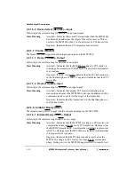
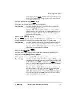
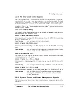
2.2.2.17 Flash Output Enable (FOE)—Output
The Flash output enable (FOE) signal is an output on the MPC8240 (and a reset
configuration input signal). Following are the state meaning and timing comments for the
FOE output signal.
State Meaning
Asserted—Enables Flash output for the current read access.
Negated—Indicates that there is currently no read access to Flash.
Note that the FOE signal provides no indication of any write
operation(s) to Flash.
Timing Comments
Assertion—The MPC8240 asserts FOE at the start of the Flash read
cycle.
Negation—Controlled by the ROMFAL and ROMNAL parameters
of the MCCR1 register.
2.2.2.18 Address Strobe (AS)—Output
The AS output signal is used as a user-defined timing signal for the Port X interface. The
assertion and pulse width are fully programmable with the ASFALL and ASRISE
parameters in the MCCR2 register. AS is also a reset configuration input signal.
State Meaning
Asserted—Programmable number of clocks (ASFALL) from the
assertion of RCS0 or RCS1.
Negated—Programmable number of clocks (ASRISE) from the
assertion of AS.
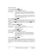
2.2.3 EPIC Control Signals
There are five EPIC interrupt control signals that have dual functions. The signals serve as
five distinct incoming interrupt requests (IRQ[0:4]) when the EPIC unit is in discrete
interrupt mode (defined by GCR[M] = 1 and EICR[SIE] = 0). When the EPIC unit is in the
serial interrupt mode (GCR[M] = 1 and EICR[SIE] = 1) or pass-through mode (GCR[M] =
0), each signal takes on an alternate function. The protocol for the various modes of the
EPIC unit are described in Chapter 11, “Embedded Programmable Interrupt Controller
(EPIC) Unit.”
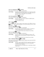
2.2.3.1 Discrete Interrupt 0:4 (IRQ[0:4])—Input
Following is the state meaning for the IRQ[0:4] signals (discrete interrupt mode). The
polarity and sense of each of these signals is programmable. All of these inputs can be
driven completely asynchronously. In pass-through mode, interrupts from external source
IRQ0 are passed directly to the processor.
Содержание MPC8240
Страница 1: ...MPC8240UM D Rev 1 1 2001 MPC8240 Integrated Processor User s Manual ...
Страница 38: ...xviii MPC8240 Integrated Processor User s Manual TABLES Table Number Title Page Number ...
Страница 48: ...xlviii MPC8240 Integrated Processor User s Manual Acronyms and Abbreviations ...
Страница 312: ...6 94 MPC8240 Integrated Processor User s Manual ROM Flash Interface Operation ...
Страница 348: ...7 36 MPC8240 Integrated Processor User s Manual PCI Host and Agent Modes ...
Страница 372: ...8 24 MPC8240 Integrated Processor User s Manual DMA Register Descriptions ...
Страница 394: ...9 22 MPC8240 Integrated Processor User s Manual I2O Interface ...
Страница 412: ...10 18 MPC8240 Integrated Processor User s Manual Programming Guidelines ...
Страница 454: ...12 14 MPC8240 Integrated Processor User s Manual Internal Arbitration ...
Страница 466: ...13 12 MPC8240 Integrated Processor User s Manual Exception Latencies ...
Страница 516: ...16 14 Watchpoint Trigger Applications ...
Страница 538: ...B 16 MPC8240 Integrated Processor User s Manual Setting the Endian Mode of Operation ...
Страница 546: ...C 8 MPC8240 Integrated Processor User s Manual ...
Страница 640: ...INDEX Index 16 MPC8240 Integrated Processor User s Manual ...

