background image

4.18 SeaTalk

ng

connections

The display can connect to a SeaTalk

ng

network.

The display can use SeaTalk

ng

to communicate with:

• SeaTalk

ng

instruments (for example, i70).

• SeaTalk

ng

pilot control head (for example, p70).

• SeaTalk

ng

autopilots (for example, Evolution

autopilots or SmartPilot SPX course computer).

• SeaTalk equipment via the optional SeaTalk to

SeaTalk

ng

converter.

• NMEA 2000 equipment via optional DeviceNet

adaptor cables.

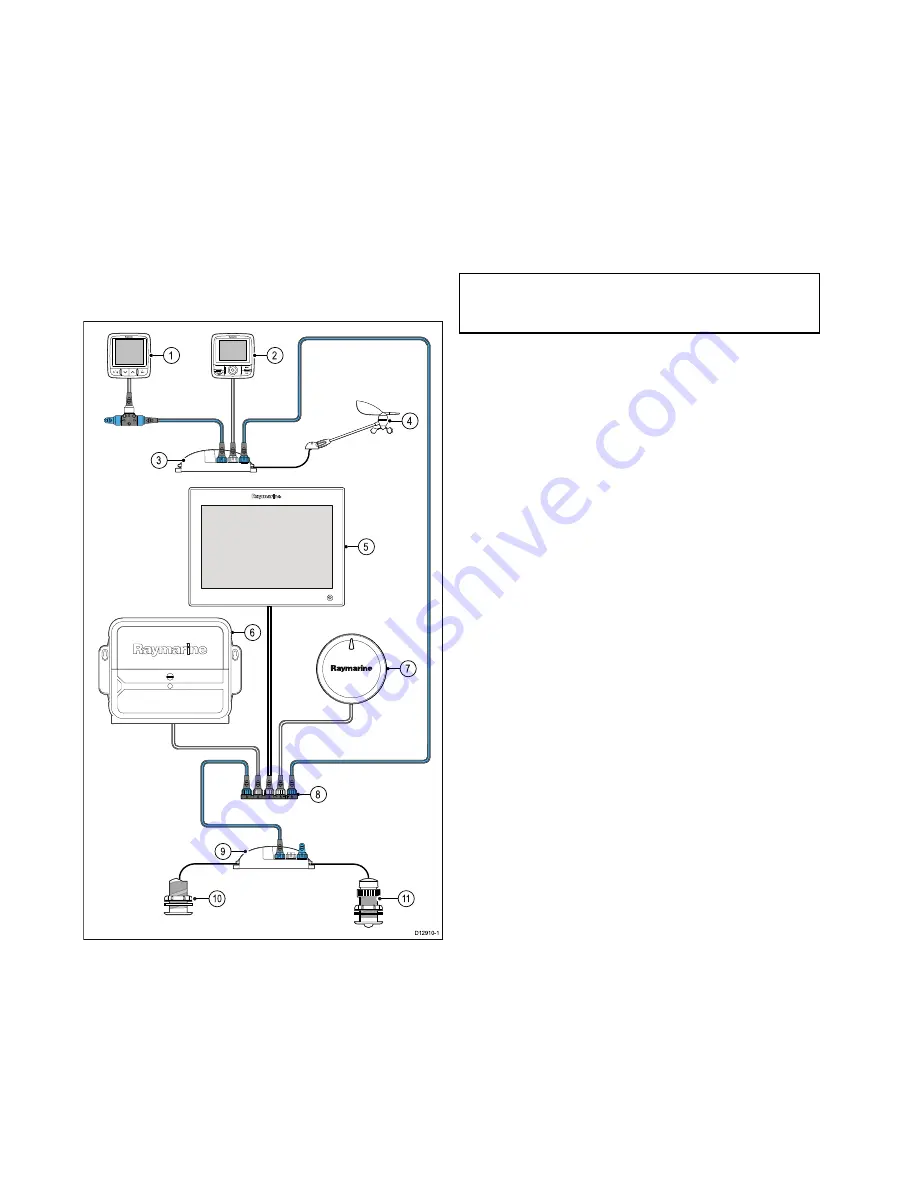
Typical SeaTalk

ng

system

D12910-1

1

0

1

1

9

1

2

4

5

6

7

8

3

00

1.

SeaTalk

ng

instrument — for example, i70.

2.

SeaTalk

ng

pilot control head — for example, p70.

3.

iTC-5 converter.

4.

Wind transducer.

5.

Multifunction display.

6.

Actuator Control Unit (ACU).

7.

EV unit.

8.

SeaTalk

ng

5 Way block.

9.

iTC-5 converter.

10. Depth transducer.

11. Speed transducer.

SeaTalk

ng

power requirements

The SeaTalk

ng

bus requires a 12 V power supply.

Power may be provided from:

• Raymarine equipment with a regulated 12 V power

supply (for example, a SmartPilot SPX course
computer); or:

• Other suitable 12 V power supply.

Note:

SeaTalk

ng

does NOT supply power to

multifunction displays and other equipment with a
dedicated power supply input.

64

gS Series

Содержание Raymarine gS 195

Страница 1: ...gS Series Installation and operation instructions English Date 01 2015 Document number 81344 7 EN 2015 Raymarine UK Limited Release 13...

Страница 2: ......

Страница 3: ...s for Auto gain offset Auto color gain offset Depth sensitivity Fishfinder Setting an auto gain offset Setting auto color gain offset Depth sensitivity Adjusting depth sensitivity Added Wind Angle and...

Страница 4: ...registered or claimed trademarks of FLIR Systems Inc All other trademarks trade names or company names referenced herein are used for identification only and are the property of their respective owner...

Страница 5: ...ower connection 48 4 5 Card reader connection 50 4 6 Auxiliary alarm connection 51 4 7 Network connections 52 4 8 Keypad connection 54 4 9 Radar connection 55 4 10 Sonar module connection 57 4 11 Ther...

Страница 6: ...radio integration 179 14 1 DSC VHF radio integration 180 14 2 Enabling DSC VHF radio integration 180 Chapter 15 Fuel manager 181 15 1 Fuel manager overview 182 Chapter 16 AIS function 185 16 1 AIS ov...

Страница 7: ...eed 324 21 15 Radar Set up menu 325 21 16 Resetting the radar 327 Chapter 22 Camera application 329 22 1 Camera application overview and features 330 22 2 Changing the camera feed 331 22 3 Displaying...

Страница 8: ...stem data troubleshooting 405 30 10 Video troubleshooting 406 30 11 Wi Fi troubleshooting 407 30 12 Bluetooth troubleshooting 408 30 13 Touchscreen troubleshooting 409 30 14 Miscellaneous troubleshoot...

Страница 9: ...rtography and a user defined Minimum Safe Depth value As both of these values are subjective the generated route MUST be carefully checked and if necessary edited BEFORE starting to follow the route i...

Страница 10: ...ected behavior designed to protect the unit from the adverse effects of excessive heat Caution Mounting surface requirements This product is heavy To prevent potential damage to the product and or you...

Страница 11: ...lor Thin Film Transistor TFT displays Water ingress Water ingress disclaimer Although the waterproof rating capacity of this product meets the stated IPX standard refer to the product s Technical Spec...

Страница 12: ...distance For optimum EMC performance we recommend that wherever possible Raymarine equipment and cables connected to it are At least 1 m 3 ft from any equipment transmitting or cables carrying radio...

Страница 13: ...identification and amateur radio stations radio stations that require license used in industries such as microwave ovens scientific medical equipment devices and production line of other factories ar...

Страница 14: ...illuminated pixels allowed refer to the product technical specification for details please contact your local Raymarine service center for further advice Warranty registration To register your Raymar...

Страница 15: ...nd product information Chapter contents 2 1 Handbook information on page 16 2 2 Handbook conventions on page 17 2 3 Product overview on page 19 2 4 System feature highlights on page 20 Document and pr...

Страница 16: ...handbook 81344 gS95 Mounting template 87173 gS125 Mounting template 87171 gS165 Mounting template 87172 gS195 Mounting template 87198 RCR 2 Mounting template 87186 Additional handbooks Description Pa...

Страница 17: ...ist or menu either by touch or physical buttons Touch Press your finger on the menu and slide up or down to scroll Physical buttons Turn the Rotary control clockwise or anti clockwise to scroll Applic...

Страница 18: ...her a Waypoint MOB button or an on screen icon WPT button c Series e Series RMK 9 keypad WPT icons a Series gS Series Throughout this manual the term Select WPT refers to pressing the physical WPT but...

Страница 19: ...y multifunction displays which do not have physical buttons can be connected to a remote keypad which allows HybridTouch functionality All functions can be accessed using the touchscreen However there...

Страница 20: ...3 7 System protocols System integration a Series c Series e Series 3 1 System integration gS Series Typical systems a Series c Series e Series 3 6 Typical systems gS Series 33 3 Network hardware Syst...

Страница 21: ...evice acts as a repeat display and intuitive control surface for your MFD Graphical representations of the MFD controls on your mobile display give you total remote control of your MFD Chapter 28 Mobi...

Страница 22: ...xth Sense at sea View the world around your vessel even in total darkness Thermal technology sees temperature not visible light This means that it sees things that the human eye can t Enhance your sit...

Страница 23: ...ch movies Watch television broadcasts such as the latest sporting event requires an external Satellite TV receiver Play videogames Playback video footage or view photos from an external digital camera...

Страница 24: ...he fuel manager Setting up fuel manager Setting the low fuel alarm Enabling the fuel range ring Simulator Mode Simulator Mode enables you to practice using your display and familiarize yourself with i...

Страница 25: ...ed devices along with software versions and serial numbers Record live data streams from the data busses SeaTalkng NMEA 0183 etc for advanced diagnostics and for sending system information to Raymarin...

Страница 26: ...26 gS Series...

Страница 27: ...ces MDS overview on page 33 3 4 Identifying your display variant on page 34 3 5 Networking constraints on page 34 3 6 Typical systems on page 36 3 7 System protocols on page 38 3 8 Data master on page...

Страница 28: ...Remote control 1 per multifunction display Raymarine RCU 3 Bluetooth 2 Smartphone Tablet device 1 per multifunction display For Raymarine wireless video streaming and remote control apps Apple iPhone...

Страница 29: ...ed or Tridata i60 Wind CH Wind i70 ST70 ST70 SeaTalk via optional SeaTalk to SeaTalkng converter i40 Wind Speed Depth or Bidata ST60 Wind Speed Depth Rudder or Compass ST40 Wind Speed Depth Rudder or...

Страница 30: ...board alert 1 basestation All Raymarine Lifetag basestations SeaTalk via optional SeaTalk to SeaTalkng converter 12 Engine interface Raymarine 1 unit for each engine CAN bus ECI 100 SeaTalkng 12 Engin...

Страница 31: ...display SeaTalkhs 18 Additional multifunction display s third party Connections to multifunction display NMEA outputs 4 Connections to multifunction display NMEA inputs 2 NMEA 0183 compatible chartpl...

Страница 32: ...Fusion entertainment systems Multiple Fusion 700 series entertainment systems MS IP700 MS AV700 SeaTalkhs 24 PC laptop 1 Windows compatible PC or laptop running Raymarine Voyage Planner software SeaTa...

Страница 33: ...is added If this exercise is NOT completed the system will automatically attempt to resolve data conflicts However this may result in the system choosing a source of data that you do not want to use I...

Страница 34: ...nated as the data master The data master display will receive data through NMEA 0183 and or SeaTalkng and bridge the data over SeaTalkhs to other networked displays Homescreen sharing When networked M...

Страница 35: ...ll be displayed until you disconnected the incompatible device from your network 3rd generation multifunction displays are not compatible with the following Raymarine displays Product Image Multifunct...

Страница 36: ...play 2 RMK 9 remote keypad 3 Radar scanner 4 Actuator Control Unit ACU 5 Attitude Heading Reference Sensor AHRS 6 Sonar module 7 GPS receiver 8 SeaTalkng pilot controller optional Example Expanded sys...

Страница 37: ...ler 6 SeaTalkng Instrument display 7 AIS receiver transceiver 8 Audio system 9 Smartphone tablet 10 Remote keypad 11 DeviceNet spur for NMEA 2000 devices 12 Network switch 13 Multifunction display 14...

Страница 38: ...o allow for a whole network of marine electronics from any manufacturer to communicate on a common bus via standardized message types and formats SeaTalk SeaTalk is a protocol which enables compatible...

Страница 39: ...lays However these connections will only become active in the event of a fault and or reassignment of the data master In an autopilot system which does not contain a dedicated pilot control head the D...

Страница 40: ...tion D12171 2 1 4 5 3 8 7 6 2 1 Power drill 2 Jigsaw 3 Pozidrive screwdriver 4 Adhesive tape 5 Spanner for surface mounting or bracket mounting fixings 6 File 7 Hole saw for flush mounting For hole sa...

Страница 41: ...ng both above and below decks Although the unit is waterproof it is good practice to locate it in a protected area away from prolonged and direct exposure to rain and salt spray Electrical interferenc...

Страница 42: ...ht 3 4 2 1 D13119 1 1 Top 2 Bottom 3 Left 4 Right LCDs can be orientated in 2 directions 1 2 D13120 1 1 12 O clock Standard orientation In the 12 O clock orientation the LCD is better viewed from top...

Страница 43: ...D 36 mm 1 4 in E 39 2 mm 1 5 in F 90 mm 3 5 in Planning the installation 43...

Страница 44: ...44 gS Series...

Страница 45: ...9 4 12 IP Camera connections on page 60 4 13 Weather receiver connection on page 61 4 14 Fusion link connection on page 61 4 15 GPS connection on page 62 4 16 AIS connection on page 63 4 17 Fastheadin...

Страница 46: ...adequate strain relief is provided Protect connectors from strain and ensure they will not pull out under extreme sea conditions Circuit isolation Appropriate circuit isolation is required for instal...

Страница 47: ...lkhs connection 4 Card reader connection 5 Analogue video Input Alarm Output 6 Power NMEA 0183 Analogue video Input 7 HD SDI Video Input 8 PoE RayNet SeaTalkhs connection Connector and cable protectiv...

Страница 48: ...he negative battery terminal connected to the vessel s ground Floating with neither battery terminal connected to the vessel s ground Warning Positive ground systems Do not connect this unit to a syst...

Страница 49: ...r products power connection Sharing a breaker Where more than 1 piece of equipment shares a breaker you must provide protection for the individual circuits E g by connecting an in line fuse for each p...

Страница 50: ...screws should be removed as follows gS95 ALL 4 plastic screws must be removed to enable the mounting brackets to be attached gS125 gS165 gS195 The plastic screw should ONLY be removed from the locatio...

Страница 51: ...liary alarm supplied 2 Multifunction display rear connector panel 3 Connection Wires should be connected Black to Black and Red to Purple 4 Video In Alarm out cable supplied The auxiliary alarm to cab...

Страница 52: ...RayNet cable supplied with the display includes a suppression ferrite 2 additional suppression ferrites are supplied with the display these must be used on any additional network connections Network...

Страница 53: ...class 2 6 49 W and deducted from the remaining power output The table below shows acceptable configurations of PoE devices Class 1 3 84 W Class 2 6 49 W Class 3 Class 0 12 95 W Total power used 1 3 84...

Страница 54: ...ble When connecting the keypad directly to a New a Series New c Series or New e Series multifunction display the keypad is not supplied with PoE and so requires power using the alternate power connect...

Страница 55: ...dar cable 5 VCM Voltage Converter Module required for Open Arrays 6 Power connection Radar connected directly to the display D12895 1 2 4 3 1 1 Radar scanner 2 Multifunction display rear connector pan...

Страница 56: ...nner s power and data connections Cable Part number RJ45 SeaTalkhs 5 m 16 4 ft Power and data digital cable A55076D RJ45 SeaTalkhs 10 m 32 8 ft Power and data digital cable A55077D RJ45 SeaTalkhs 15 m...

Страница 57: ...ule have a locking weather tight mechanism Direct sonar module connection On smaller systems with only 3 network devices the sonar module may be connected directly to the display 2 1 SeaT alkhs RayNet...

Страница 58: ...details which multifunction display variants feature a built in sonar module and can be connected directly to compatible sonar transducers Non sonar variants Sonar variants DownVisionTM variants a65...

Страница 59: ...thermal infrared and 1 for visible light If you only have 1 display you should only connect the video cable labelled VIS IR visible light infrared to the display If you have 2 or more displays you sh...

Страница 60: ...4 4 4 4 5 5 5 5 3 Item Description 1 Multifunction display 2 Network switch 3 RayNet to RJ45 adaptor cables A62360 A80151 A80159 4 CAM200IPs 5 Ethernet couplers R32142 Note Network switches do not pr...

Страница 61: ...m 4 14 Fusion link connection You can connect a Fusion 700 series marine entertainment system to your multifunction display Direct connection 2 3 4 D12903 1 1 1 Multifunction display 2 Fusion system 3...

Страница 62: ...displays Note The Fusion entertainment system can be controlled by any compatible networked multifunction display when connected using a network switch 4 15 GPS connection The multifunction display c...

Страница 63: ...4 17 Fastheading connection If you wish to use MARPA radar target acquisition functions on your multifunction display you need either An autopilot connected to the multifunction display via SeaTalkng...

Страница 64: ...9 1 2 4 5 6 7 8 3 0 0 1 SeaTalkng instrument for example i70 2 SeaTalkng pilot control head for example p70 3 iTC 5 converter 4 Wind transducer 5 Multifunction display 6 Actuator Control Unit ACU 7 EV...

Страница 65: ...SeaTalkng backbone NMEA2000 12V D12911 1 1 2 4 3 SeaT alkng 1 12 V supply into backbone 2 SeaTalkng backbone 3 SeaTalkng to DeviceNet adaptor cable 4 NMEA 2000 equipment Connecting the display to an e...

Страница 66: ...connected to the display s Port 1 OUTPUT both NMEA devices must be using the same baud rate You can connect up to 4 NMEA 0183 devices to the display s NMEA 0183 OUTPUT Port 1 You can connect a total o...

Страница 67: ...or digital video player will require speakers to be connected to the players audio output 4 23 HDMI video output The HDMI cable is used to output a gS multifunction display s screen to an external dis...

Страница 68: ...BNC connector and onto the cable however care must be taken not to split the protective boot HD SDI connection 1 2 3 D13046 3 1 75 ohm BNC connector Supplied 2 Boot Supplied 3 Data cable not supplied...

Страница 69: ...into discovery mode 5 Ensure Bluetooth is enabled on your external media player device and ensure it is ready to be paired For more information consult the instructions that accompany the device 6 On...

Страница 70: ...first Enable Bluetooth in the System Settings on the multifunction display Pair the remote control unit with the multifunction display Operating principles Remote control operating principles Only 1...

Страница 71: ...nit in the list of devices 9 When prompted press the arrow button on your remote that you wish to be configured as the UP button The other arrow button will automatically be configured as the DOWN but...

Страница 72: ...in homescreen in left to right top to bottom order Press UP or DOWN arrow for momentary response Hold UP or DOWN arrow for continuous response Toggle menu items and options in dialogs and prompts in...

Страница 73: ...u power off the multifunction display it loses its connection with the RCU 3 after 10 minutes 10 M inutes 10 15 20 25 30 M inutes 35 40 45 50 55 60 5 3 To restore the connection between the 2 units pr...

Страница 74: ...running the Navionics mobile marine app The synchronization downloads Navionics Freshest Data from your mobile device to your MFD and uploads sonar logs from your MFD to your mobile device Waypoints a...

Страница 75: ...e locations on page 76 5 2 Mounting surface requirements on page 76 5 3 Flush mounting the display on page 77 5 4 Flush mounting the card reader on page 78 5 5 Surface mounting the display on page 79...

Страница 76: ...d but is used in searches This product is heavy To prevent potential damage to the product and or your vessel observe the following BEFORE installing the product Refer to the weight information provid...

Страница 77: ...re that the unit fits into the removed area and then remove any rough edges 8 Affix the supplied gasket onto the rear of the display and press firmly onto the flange 9 Connect the power data and other...

Страница 78: ...as indicated on the mounting template to accept the fixings 5 Using a 40 mm 1 6 in hole cutter drill out the cut out area identified on the mounting template 6 Follow the rebate cut out line on the te...

Страница 79: ...ed gasket onto the rear of the display and press firmly onto the flange 8 Connect the power data and other cables to the unit 9 Attach the supplied mounting brackets to the rear of the display using t...

Страница 80: ...ing or self adhesive tape 4 Drill 4 holes as indicated on the mounting template to accept the fixings 5 Using a 40 mm 1 6 in hole cutter drill out the cut out area identified on the mounting template...

Страница 81: ...en controls on page 89 6 7 Screen overview on page 90 6 8 Basic touchscreen operations on page 93 6 9 Multi Touch gestures on page 94 6 10 Initial set up procedures on page 94 6 11 Enabling autopilot...

Страница 82: ...ote To ensure user safety the PowerSave feature will not be available if any connected radars are switched on the multifunction display is providing autopilot control in a system without a dedicated p...

Страница 83: ...out 6 Range In press to range in 7 Switch Active press to switch the active pane or to switch the active multifunction display in multiple display systems 8 WPT MOB press and release to access the way...

Страница 84: ...ssing the MENU button Using the cursor The cursor is used to move around the screen D7366_3 The cursor appears on the screen as a white cross D7368_2 If the cursor has not been moved for a short perio...

Страница 85: ...configure application pages and display preferences 4 Set up select this icon to access the system set up menus 5 Icon each icon represents an application page A page can display multiple application...

Страница 86: ...ner Timed Trans mit Scanner switches between on transmitting and standby mode Scanner goes into power save mode when constant use of radar is not required AIS status symbols AIS status is indicated by...

Страница 87: ...fter power up Last page The page last viewed is displayed after power up Choose page The page you select will be displayed after power up 4 If selecting Choose page the Homescreen is displayed 5 Selec...

Страница 88: ...vide higher levels of detail and 3D views Fishfinder application with a transducer and a sonar variant multifunction display or compatible Sonar Module you can use the fishfinder application to help y...

Страница 89: ...ge you can select the active application and view it fullscreen by following the steps below With a page featuring multiple applications displayed 1 Touch anywhere inside the application you want to m...

Страница 90: ...to access the homescreen 2 Databar provides information about your vessel and its environment The position and type of information in the databar can be customized from the Homescreen Customize Datab...

Страница 91: ...data items such as waypoints and routes D12277 2 1 4 5 2 3 Screen item Description 1 Back Displays with a touchscreen Select the onscreen Back icon to go back to the previous menu Non touchscreen or H...

Страница 92: ...3 For characters that have multiple available accents use the character key to toggle between them 4 Select the key to enter the character Numeric menu items Numeric menu items display numeric data an...

Страница 93: ...ected autopilot unit to perform specific functions 3 Close Closes the control dialog 6 8 Basic touchscreen operations Placing and moving the cursor using touch To place or move the cursor around the s...

Страница 94: ...ends that you perform an initial set up procedure Startup wizard When you power up the display for the first time or after a system reset a Startup Wizard is displayed The wizard guides you through th...

Страница 95: ...ken into account when calculating a Safety Margin are Vessel maneuvering characteristics A vessel s draft increases due to squat trim roll pitch and heave Chart accuracy The electronic chart depth may...

Страница 96: ...de by following the steps below With the homescreen displayed 1 Select Set Up 2 Select System Settings 3 Select Simulator 4 Select On to turn simulator mode on or 5 Select Off to turn simulator mode o...

Страница 97: ...l will switch the control between On and Off On a system containing multiple displays the pilot control is enabled on all displays at the same time Enabling the autopilot control function Evolution au...

Страница 98: ...th an ECI interface and Using the engine identification wizard information Make the data connections according to the instructions provided in the 87202 ECI Installation instructions Ensure all data b...

Страница 99: ...ternal Devices Engines Set up 2 If required change the number of engines your vessel has by selecting Num of Engines and entering the correct number of engines You can select up to 5 engines 3 Select...

Страница 100: ...erences are applicable to the following devices MFDs networked using SeaTalkhs MFDs networked using SeaTalkng SeaTalkng instruments displays networked using SeaTalkng SeaTalk instruments displays netw...

Страница 101: ...sion of your Raymarine products 3 If the software on the website is newer than the software on your products download the relevant software package 4 Insert the MicroSD card into your PC or Mac card r...

Страница 102: ...u get the most out of your products Video tutorials Raymarine official channel on YouTube http www youtube com u ser RaymarineInc Video Gallery http www rayma rine co uk view id 2679 Product Support v...

Страница 103: ...nts 7 1 GPS Check on page 104 7 2 GPS Status on page 104 7 3 Raymarine GPS GNSS receiver compatibility on page 105 7 4 Radar check on page 106 7 5 Sonar check on page 107 7 6 Thermal camera setup and...

Страница 104: ...een Set up System Settings GPS Set up For each satellite the screen provides the following information 1 2 3 D13122 1 1 Sky view 2 Satellite status 3 Position and fix information Sky view Sky view is...

Страница 105: ...ed by the position fix in UTC format Mode Identifies wether the receiver is working in differential mode or non differential mode Datum The receiver s datum setting affects the accuracy of the vessel...

Страница 106: ...ures that radar objects appear at the correct bearing relative to your boat s bow You should check the bearing alignment for any new installation Example misaligned radar D11590 2 1 2 Item Description...

Страница 107: ...ou want to use Selecting the speed transducer With the fishfinder application displayed 1 Select Menu 2 Select Set Up 3 Select Transducer Set Up 4 Select Speed Transducer A list of transducers is disp...

Страница 108: ...ontrol Unit JCU and PoE Power over Ethernet injector ensure these units are also connected correctly Set up the camera You will need to Adjust the image contrast brightness and so on Check camera move...

Страница 109: ...in and out Resetting the thermal camera to the home position When connected to a pan tilt thermal camera the home position of the camera can be set In the thermal camera application 1 Select Menu 2 Se...

Страница 110: ...110 gS Series...

Страница 111: ...12 8 2 Inserting a memory card or chart card on page 112 8 3 Removing a memory card or chart card on page 113 8 4 Saving user data and user settings on page 113 8 5 Save and restore items on page 116...

Страница 112: ...lass 10 or UHS Ultra High Speed class memory cards Chart cards Your product is pre loaded with electronic charts worldwide base map If you wish to use different chart data you can insert compatible ch...

Страница 113: ...a Each route can be saved separately Tracks user data Each track can be saved separately User settings Saves the settings you ve made in the set up menus to a single archive file Only 1 user settings...

Страница 114: ...g you to select the slot you want to save data to if your display only has 1 card slot then you will not be prompted 10 Select SD1 for a memory card in the top card slot or SD2 for a memory card in th...

Страница 115: ...or select Erase All A message is displayed prompting you for confirmation 6 Select Yes to proceed with the deletion or No to cancel the operation Backing up user settings to a memory card With the Hom...

Страница 116: ...of Fuel Tanks Number of Batteries Customize Units Set up Distance units Speed Units Depth Units Temperature Units Pressure Units Volume Units Economy Units Wind Speed Units Customize Time and Date Set...

Страница 117: ...y contour Depth contour Deep water color Radar application Menu Setting Presentation Range rings Presentation Databoxes Databox 1 Databox 1 content Databox 2 Databox 2 content Fishfinder application M...

Страница 118: ...displayed 4 Use the file browser to locate the file on the MicroSD card 5 Select the file you want to view The file will now open 6 Select Back or Close to close the image 8 7 Resetting your system Yo...

Страница 119: ...e 120 9 2 Boat details on page 121 9 3 Units set up on page 122 9 4 Time and Date set up on page 123 9 5 Display preferences on page 124 9 6 Databar and databox overview on page 126 9 7 List of data i...

Страница 120: ...egian Polish Portuguese Brazilian Russian Slovenian Spanish Swedish Turkish With the Homescreen displayed 1 Select Customize 2 Select Language 3 Select your language from the list of languages Languag...

Страница 121: ...ting feature 1 0 to 50 0 Num of Engines Allows you to specify the number of engines your vessel has This setting determines the number of engines shown in the engine data application 1 to 5 Num of Fue...

Страница 122: ...for the display of all values related to temperature Fahrenheit Celsius Pressure Units The units of measure that will be used in all applications for the display of all values related to pressure Bar...

Страница 123: ...te information in all applications MM DD YY Month Day Year DD MM YY Day Month Year Time Format Allows you to specify the preferred format for the display of time information in all applications 12hr 2...

Страница 124: ...isplay the onscreen range in and range out icons Note Onscreen range controls are not available on non touchscreen displays Onscreen range controls cannot be hidden on touch only displays Show default...

Страница 125: ...shared brightness function see list of compatible units above Before a unit can respond to a shared brightness adjustment it must be assigned to the relevant Brightness Group A single unit can only be...

Страница 126: ...sible onscreen Auto hide the databar On multifunction displays that have a touchscreen the databar that is displayed at the top of all applications pages can be set to auto hide This provides a larger...

Страница 127: ...the cell For example Depth data 6 Select the data item The data you selected is displayed on screen in the appropriate cell 7 Select Home or Back when completed Displaying status icons in the databar...

Страница 128: ...ata application Graphics Battery Amps Battery Temperature Battery Voltage Battery Battery status Battery Charge Rate of Turn Heel Angle Boat Types of data generated by your vessel For example tank lev...

Страница 129: ...Pressure Oil Pressure Coolant Temperature Transmission Oil Temperature Transmission Oil Pressure Transmission Gear Boost Pressure Fuel Pressure Fuel Flow Rate Fuel Flow Inst Fuel Flow Avg Engine Hours...

Страница 130: ...o Empty Fuel Used Trip Fuel Types of data related to the fuel system For example fuel levels Fuel Used Season Pressure Air Temperature Minimum Air Temperature Maximum Air Temperature Drift Set Set Dri...

Страница 131: ...only Locked Heading Locked Heading Error LH Error and LH Data application only Tack Heading Heading Heading related data For example locked heading Compass Data application only Cursor Position Only...

Страница 132: ...Course Made Good CMG DMG CMG VMG Data application only Distance to Waypoint Distance Made Good Waypoint ETA Waypoint TTG Route ETA Route TTG Pilot Pilot related data For example rudder Rudder Angle Sp...

Страница 133: ...Well Local Time Time Time related data For example local time Local Date AWA Maximum AWA Minimum AWA AWS Maximum AWS Minimum AWS TWA Maximum TWA Minimum TWA TWS Maximum TWS Minimum TWS TWD Cardinal W...

Страница 134: ...te Dials and graphical representations are only available from the Data application Databar and data cell overlays can only display digital items Note The Battery Engine Fuel and Tanks menus will disp...

Страница 135: ...plays the Pilot Control dialog Only available when a Raymarine autopilot is detected on the system and Autopilot Control is set to On Pilot Response Enables selection of the pilot response level when...

Страница 136: ...onnected devices Refer to the External devices menu section of the manual Wireless Connections Provides access to the Wi Fi and bluetooth connection options Refer to the Wireless connections menu sect...

Страница 137: ...satellite fix can be acquired D Fix A differential beacon fix has been acquired SD Fix A differential satellite fix has been acquired Position Displays the latitude and longitude position of your rece...

Страница 138: ...on may result in the system choosing a source of data that you do not want to use Device selection Menu item Description GPS Enables you to search for any externally connected GPS devices and select t...

Страница 139: ...s menu item is only available when an AIS unit is detected or when Simulator mode is On For an explanation of these options refer to the AIS menu options described in the AIS section of this document...

Страница 140: ...ng WiFi devices using an encrypted connection If you want to prevent unauthorized devices from connecting to your display you must specify the same SSID for both the multifunction display and the wire...

Страница 141: ...Menu item Description Options Viewing only RayView Remote Control RayRemote or RayControl Remote Control Customizing your display 141...

Страница 142: ...receive heading data from the external heading sensor On Off default NMEA Output Settings Allows you to enable or disable the individual NMEA sentences that are sent by the multifunction display to an...

Страница 143: ...ot the datum used by your paper charts you can change the datum used by your multifunction display When you change the datum for your multifunction display the chart grid will subsequently move accord...

Страница 144: ...faces Data Master Any system containing more than one networked multifunction display must have a designated data master The data master is the display which serves as a primary source of data for all...

Страница 145: ...oftware Sirius If connected to a Sirius weather receiver this option enables you to view Sirius weather statistics Save Logs Allows you to save error logs to a MicroSD card for troubleshooting purpose...

Страница 146: ...146 gS Series...

Страница 147: ...Chapter 10 Document viewer application Chapter contents 10 1 Document viewer overview on page 148 Document viewer application 147...

Страница 148: ...o Width Scales the open document to fit the width of the application window Close File Closes the open document Opening the user manual The product user manual is stored on the internal memory From th...

Страница 149: ...ge the zoom factor Selecting a page You can skip to the page you want to view by entering the page number With a pdf document open 1 Select Menu 2 Select Go to page The numeric keypad is displayed 3 E...

Страница 150: ...tool bar and return to the normal viewing Keyword not found The document viewer will let you know if the keyword you have searched for does not appear in the document If the keyword is not found then...

Страница 151: ...current locked heading on page 153 11 5 Disengaging the autopilot on page 154 11 6 Manually displaying the pilot control dialog box on page 155 11 7 Pilot Control dialog on page 155 11 8 Pilot Bar on...

Страница 152: ...10 Pilot settings Manage autopilot alarms 11 13 Autopilot alarms Note In a system that does not include a dedicated Pilot control head the Data Master MFD cannot be switched Off or put into PowerSave...

Страница 153: ...e Goto Cursor Goto Waypoint or Follow Route as appropriate The Pilot Control dialog is displayed 2 Select Yes Track Engaging the autopilot using the context menu You can engage the autopilot in track...

Страница 154: ...ngaged put into standby and the Pilot Control dialog is displayed Disengaging the autopilot using the pilot button On multifunction displays which have a dedicated pilot button or when using a remote...

Страница 155: ...ing Pilot Control dialog Auto The example below shows the Pilot Control dialog options when Auto locked heading has been engaged D12882 1 1 2 3 4 5 6 8 7 Description 1 Pilot Status Current pilot mode...

Страница 156: ...Advance Waypoint from the context menu 6 When you are following a route or going to a waypoint or cursor position and select Menu Navigate Stop Goto Stop Follow or Advance Waypoint 7 When you arrive a...

Страница 157: ...Pilot settings include the following options Vessel Settings Drive Settings Sail Boat Settings Commissioning Initial setup and commissioning Vessel settings The vessel settings are designed to provid...

Страница 158: ...k the steering compass 2 Check the autopilot heading on your multifunction display 3 From the Pilot Set up page select Pilot Settings 4 Select Vessel Settings 5 Select Compass Offset 6 Adjust the Comp...

Страница 159: ...ansducer Note To perform this procedure it is desirable to have a networked device such as an instrument pilot control head or multifunction display that can display the current rudder position onscre...

Страница 160: ...and connected in accordance with the associated Installation instructions Check also that the commissioning engineer is familiar with the installation and components of the autopilot system including...

Страница 161: ...ard ensure the pilot is in standby mode and then from the Pilot Set up page 1 Select Pilot Settings 2 Select Commissioning 3 Select Dockside Wizard Selecting a drive type Drive type selection is avail...

Страница 162: ...sting the hard over time On vessels without a rudder reference transducer it is important to set the hard over time limits correctly to ensure accurate autopilot operation Hard over time is the time i...

Страница 163: ...compass offset value using the pilot control head or multifunction display and fine tune the heading to an accurate value Note Do NOT rely on the heading accuracy until you are satisfied that compass...

Страница 164: ...y the autopilot the multifunction display provides an audible alarm sound providing that the alarm has not already been silenced The Pilot Control dialog is displayed indicating a new alarm Additional...

Страница 165: ...Chapter 12 Alarm management Chapter contents 12 1 Alarms overview on page 166 12 2 Alarm Manager overview on page 166 12 3 Alarm options on page 169 Alarm management 165...

Страница 166: ...e alarm event i e an alarm message is displayed 1 Select Ok The message is dismissed and the alarm tone is stopped Tip If an alarm message includes an Edit button then the alarm s settings can be acce...

Страница 167: ...t the Settings tab 2 Select the alarm category for the alarm you want to enable disable Alarms are displayed in the Alarm Manager in the following categories Safety Alarms General Alarms Switch Panel...

Страница 168: ...u can also change the unit of measure for the alarm threshold you are currently changing by selecting on the relevant unit of measure from the numeric keypad Clearing the alarm history You can view th...

Страница 169: ...ed during active navigation an alarm is triggered when your vessel steers off track more than the value you specify for the Off Track XTE setting Enable Enabled Ticked Disabled Un ticked default Off T...

Страница 170: ...m will not be triggered until the Fuel Manager is enabled Note You cannot set LFR to be more than the current TFC value Enable Enabled Ticked Disabled Un ticked default Fuel level Default value If Tot...

Страница 171: ...connected sonar module Fishing deep water arrival When enabled an alarm is triggered when the depth reaches the value specified in the Deep Limit alarm setting This option is only available when curre...

Страница 172: ...Default values 0 6 m 2 ft 0 3 fa default Range 0 6 m to Fish alarm deep limit 2 ft to Fish alarm deep limit 0 3 fa to Fish alarm deep limit Fish alarm deep limit Default values 305 m 1 000 ft 167 fa...

Страница 173: ...er specific error message Unknown error 2 manufacturer specific error message Unknown error 3 manufacturer specific error message Unknown error 4 manufacturer specific error message Unknown error 5 ma...

Страница 174: ...174 gS Series...

Страница 175: ...Chapter 13 Man Overboard MOB Chapter contents 13 1 Man overboard on page 176 Man Overboard MOB 175...

Страница 176: ...igation to any active waypoint is stopped and any existing navigation function is cancelled If position or heading and speed information is available a MOB waypoint is placed at the current vessel pos...

Страница 177: ...y with physical buttons or when using a remote keypad you can cancel the MOB alarm and resume normal operation follow the steps below 1 Press and hold the WPT MOB button for 4 seconds The MOB alarm is...

Страница 178: ...178 gS Series...

Страница 179: ...Chapter 14 DSC VHF radio integration Chapter contents 14 1 DSC VHF radio integration on page 180 14 2 Enabling DSC VHF radio integration on page 180 DSC VHF radio integration 179...

Страница 180: ...s provided to clear the message place a waypoint on the chart at the GPS position of the distressed vessel or immediately start navigating Goto Vessel to the GPS position of the distressed vessel Posi...

Страница 181: ...Chapter 15 Fuel manager Chapter contents 15 1 Fuel manager overview on page 182 Fuel manager 181...

Страница 182: ...Select All tanks full Log each subsequent fuel fill whether partial or full Note Fuel manager estimates the amount of fuel onboard based on the user logging each time you fill up the total fuel capac...

Страница 183: ...o that On is highlighted Selecting Low Fuel will turn the low fuel alarm On or Off 5 Select Fuel Level The fuel level numeric adjust control is displayed 6 Adjust the fuel level to the required value...

Страница 184: ...2 Select Presentation 3 Select Overlays 4 Select Fuel Range Ring so that On is selected The fuel range ring pop up message is displayed 5 Select OK to turn on the fuel range rings 184 gS Series...

Страница 185: ...S vectors on page 188 16 6 AIS status symbols on page 189 16 7 AIS silent mode on page 189 16 8 AIS target symbols on page 190 16 9 Displaying detailed AIS target information on page 191 16 10 Viewing...

Страница 186: ...f travel and the distance it will travel over a specified period of time COG SOG vector Targets displayed with their vectors are referred to as active targets and are scaled according to the size of t...

Страница 187: ...n display using NMEA0183 or SeaTalkng depending on the AIS unit If connecting using NMEA0183 you will now need to specify the 38 400 baud setting homescreen Set up System Settings NMEA Set up for the...

Страница 188: ...e relevant option from the list From the Display AIS Targets menu you can switch on All AIS targets only Dangerous AIS targets or switch AIS targets Off 16 5 Displaying AIS vectors You must have the c...

Страница 189: ...data to other AIS receivers but still wish to receive data from other vessels Note Not all AIS equipment supports silent mode For more information refer to the documentation that accompanies your AIS...

Страница 190: ...CPA TCPA value uncertain Lost target When the signal of a dangerous target not received for 20 seconds Target in latest predicted position Alarms sounds if enabled Target flashes Buddy target Target h...

Страница 191: ...th only the AIS overlay enabled go to Menu AIS Options Targets View AIS List From the Chart application when the Radar overlay is also enabled go to Menu Radar AIS Options Targets View Targets Lists V...

Страница 192: ...ding vessel s position Goto Waypoint Note You will NOT receive any safety messages in Simulator mode homescreen Set up System Settings Simulator Showing the Safe Zone Ring in the Chart application To...

Страница 193: ...vector lines displayed depends on the distance that an AIS target travels in the time period that you specify for this setting 0 5 min 1 min 3 min 6 min 12 min 30 min 60 min Target History Targets pr...

Страница 194: ...racking feature enables you to add AIS equipped friends and regular contacts to a Buddy List on your multifunction display As soon as a vessel on your Buddy List sails into the range of your AIS unit...

Страница 195: ...a buddy s details From the chart or radar application 1 Select the AIS buddy target The AIS buddy context menu is displayed 2 Select View Buddy List 3 Select the buddy you wish to edit The Buddy opti...

Страница 196: ...196 gS Series...

Страница 197: ...acks Chapter contents 17 1 Waypoints overview on page 198 17 2 Routes on page 207 17 3 Tracks on page 215 17 4 Import and Export on page 217 17 5 Waypoints routes and tracks storage capacity on page 2...

Страница 198: ...on both active and inactive waypoints are shown An active waypoint is the one that you are navigating to D11759 3 2 1 3 1 Inactive waypoint 2 Active waypoint 3 Alternate waypoint symbols The default w...

Страница 199: ...The context menu is displayed 2 Select Place Waypoint The Waypoint Saved dialog is displayed 3 Select the Symbol field to change the symbol that will be used to display the waypoint in the Chart or Ra...

Страница 200: ...ypoint groups Waypoints are organized into groups By default all waypoints are placed in the UNSORTED group New waypoint groups can be created and each waypoint can be assigned to a waypoint group For...

Страница 201: ...ymbol that you want to use for the waypoints in the selected group A confirmation dialog is displayed 4 Select Yes to apply the new symbols to the waypoints or select No to cancel Moving a waypoint to...

Страница 202: ...he waypoint list is displayed Note The waypoint list can also be accessed directly from the Homescreen by selecting WPT or by going to the My Data menu and selecting Waypoint List Editing waypoint det...

Страница 203: ...sting or new waypoint group or assign all of the waypoints the same waypoint symbol Searching for waypoints by name or keyword Waypoints can be searched for by name or keyword From the Waypoints list...

Страница 204: ...elected area If the box is drawn in the wrong place you can draw a new area by selecting 2 new corner points 8 Select Search from the menu A list of all waypoints in the selected area is displayed 9 S...

Страница 205: ...1 Star Fish 2 Star Fish 3 Star School Fish Lobster Small Fish Rocks Reef Private Reef Public Reef Dolphin Shark Billfish Tank Reef Ball Sailboat Sportsfisher Trawler Swimmer Martini Tree Tower Hill o...

Страница 206: ...or symbols will be displayed if Hide is displayed in the list then the group or symbols are not displayed in the application 5 Repeat Step 4 for each waypoint group or symbol type you want to show or...

Страница 207: ...active Building a route You can build a route on a touchscreen multifunction display by following the steps below D11762 1 From the chart application 1 Select and hold a location on screen The chart c...

Страница 208: ...recorded track When a track is converted the system creates the closest route through the recorded track using the minimum number of waypoints Each waypoint created will be saved with the depth and te...

Страница 209: ...a user defined Minimum Safe Depth value As both of these values are subjective the generated route MUST be carefully checked and if necessary edited BEFORE starting to follow the route in the Chart ap...

Страница 210: ...ute list Reviewing the route list is not an adequate method of checking a route please refer to Reviewing a route generated using Autorouting for details on how to check a route Once finished routes g...

Страница 211: ...voided Important Autorouting will NOT be used when moving waypoints within routes extra care should be taken to ensure that the route leg and any moved waypoints are safe to navigate 4 Scroll over the...

Страница 212: ...he start and end waypoints will be created and joined with a straight route leg however there will be no automatically generated waypoints and the waypoint symbols will be changed to caution symbols P...

Страница 213: ...select the required route from the list From the Homescreen select My Data Routes and select the required route from the list Adding a waypoint to a route on the chart screen From the chart applicati...

Страница 214: ...Follow Route Follow Route In Reverse Hide Route Insert Waypoint Edit Route Erase Route Add Route Leg Acquire Target only available if Radar overlay is switched on When following a route the context me...

Страница 215: ...Auto Time Distance Track Interval specifies the interval value e g 15 minutes For example when creating a track for a long journey an interval set to Auto could result in rapid use of all of the stor...

Страница 216: ...want to erase 3 Select Erase Track The erase track pop up message is displayed 4 Select Yes to confirm or No to cancel the action Erasing all tracks From the Homescreen 1 Select My Data 2 Select Impo...

Страница 217: ...ata and user settings 17 5 Waypoints routes and tracks storage capacity The display can store the following quantities of waypoints routes and tracks Way points 3000 waypoints 100 waypoint groups each...

Страница 218: ...218 gS Series...

Страница 219: ...chart display on page 228 18 7 Chart Orientation on page 229 18 8 Chart motion mode on page 230 18 9 Chart views on page 231 18 10 Chart display on page 233 18 11 Overlays on page 234 18 12 Chart vect...

Страница 220: ...e Chart application 18 8 Chart motion mode Chart application synchronization Wireless electronic chart plotter sync and waypoint sync with Navionics Mobile Marine app Navionics mobile marine app Plan...

Страница 221: ...ion the Call out by swiping your finger over another area or object Chart context menu The context menu provides positional data for the cursor position in relation to your vessel and access to menu o...

Страница 222: ...ffer new chart types and regions from around the globe Refer to the Raymarine website www raymarine com for the latest information on available LightHouse charts Raster charts Raster charts are an exa...

Страница 223: ...n be resumed rather than downloading the entire file again 9 Wait for the download to finish The downloaded file can now be unzipped extracted to memory card for use with your multifunction display Un...

Страница 224: ...nics cartography types are available for your multifunction display Ready to Navigate Silver Gold Gold Platinum Platinum Fish N Chip Hotmaps To check the current availability of Navionics chart cards...

Страница 225: ...options The chart application provides features to help navigate to a chosen location The navigation options are found in the Navigate menu Menu Navigate Pilot Controls Accesses the Pilot Control Dia...

Страница 226: ...navigating a route then the next waypoint is selected Note You can set the radius distance of the waypoint arrival circle which is used to trigger the waypoint arrival alarm Changing destination duri...

Страница 227: ...ayed 2 Select Advance Waypoint Note If the current destination is the last waypoint the chart advances on to the first waypoint in the route 18 4 Chart ranging and panning Ranging in and out The table...

Страница 228: ...n screen by the vessel symbol The vessel symbols are only displayed when heading or COG data is available The vessel symbol varies depending on selected settings and the availability of heading data M...

Страница 229: ...f there is active navigation Note To prevent continuous backwards and forwards rotations as the vessel yaws from side to side the chart will not update unless the heading changes by at least 10 degree...

Страница 230: ...re moves relative to your vessel You can use the Menu Presentation View Motion Boat Position menu options to determine whether the vessel is fixed in the center of the window or offset If you change t...

Страница 231: ...rt objects and move around the chart area 11 Target waypoint current target waypoint 12 Databoxes used to display data such as depth on the chart screen Item Description 13 AIS target a vessel broadca...

Страница 232: ...s below From the Chart application menu 1 Select Presentation 2 Select View Motion 3 Select 3D Display Options 4 Select Center of View so that On is highlighted Selecting centre of view will switch th...

Страница 233: ...ption determines the level of detail that is displayed on screen The Chart display menu option is only available when using vector based cartography The Chart display options are shown below Simple De...

Страница 234: ...overlay is not available in 3D view 2D Shading Determines whether terrain shading is displayed in 2D view Community Edits Determines whether the community layer is enabled or disabled Chart Text Deter...

Страница 235: ...s using COG then OVL COG is displayed in the top left corner of the Chart application Note When the overlay is using COG misalignment of the Radar and Chart images can occur due to tide and current ef...

Страница 236: ...d Sea The chart display is redrawn showing the new overlay selection NOWRad weather overlay With a suitable weather receiver connected to your multifunction display you can overlay NOWRad weather info...

Страница 237: ...s 3 Select Chart Grid so that On is selected to turn the grid on or 4 Select Chart Grid so that Off is selected to turn the grid off 2D shading If supported by your cartography type you can switch sha...

Страница 238: ...hart text Off The default setting for Chart text is On Switching chart text on and off The Chart text can be switched on and off by following the steps below From the Chart application menu 1 Select P...

Страница 239: ...ne Ring will switch the zone ring between hidden to visible Setting up the Safe Zone Ring You can adjust the Safe Zone Ring radius the time to Safe Zone and choose whether AIS targets trigger the Safe...

Страница 240: ...lect Fuel Range Ring so that Off is selected Changing the size of the vessel symbol The vessel symbol size can be changed following the steps below From the Chart application menu 1 Select Presentatio...

Страница 241: ...course A double arrow head is used if the vector length is set to a value other than infinite Note If Speed Over Ground SOG or heading data is not available vectors cannot be displayed Vector length...

Страница 242: ...Detail disables the following objects and overlays 2D Shading Community Edits Chart Text Chart Boundaries Light Sectors Routing Systems Caution Areas Marine Features Land Features Panoramic Photo Road...

Страница 243: ...navigation mark symbols are used International or US These symbols correspond to paper charts Light Sectors Determines whether the sector of light cast by a fixed beacon is displayed Routing Systems...

Страница 244: ...object on screen and choose Chart Objects from the chart context menu to view information about the selected object Select Find Nearest from the chart context menu to search for objects close by Disp...

Страница 245: ...default date Navionics animated currents Example current animation Arrows are used to indicate the direction of current flow The length of the arrow indicates the flow rate and the color of the arrow...

Страница 246: ...The electronic charts may allow animation of the tide information tide stations Animated tide information is available in the chart application wherever a diamond shaped symbol with a T is displayed T...

Страница 247: ...the graph indicates when nightfall occurs 6 Low High Tide Indicates the time at which low or high tide occurs 7 Date navigation Use the icons to move to the next or previous day 8 Time The horizontal...

Страница 248: ...m Determines the depth at which the Safety contour is displayed The Safety contour cannot be set to a value less than the Shallow contour or higher than the Deep contour Deep Water From Determines the...

Страница 249: ...dicated by CHRT Sync in the chart application title bar Any changes made to the heading range or position in any chart instance will be reflected in all other chart instances Note When the 2D and 3D c...

Страница 250: ...On and Off 6 Select Back or Ok to close the measure menu leaving the current measurement on screen Measuring from point to point From the chart application 1 Select the location on screen that you wan...

Страница 251: ...19 9 SideVisionTM Range on page 264 19 10 Fishfinder scrolling on page 264 19 11 Fishfinder display modes on page 265 19 12 SideVisionTM Views on page 267 19 13 Presentation menu options on page 268...

Страница 252: ...sion technology CHIRP DownVisionTM overview SideVision technology CHIRP SideVision overview Fishfinder features Supports multiple active sonar modules 19 4 Multiple sonar module support Create custom...

Страница 253: ...Multiple pages can be set up on the Homescreen which can be used to display different combinations of Channel and Display mode Fishfinder context menu The Fishfinder application context menu displays...

Страница 254: ...to target resolution bottom detection even through bait balls and thermoclines and detection sensitivity D12601 2 CHIRP Sonar overview CHIRP sonar produces a conical shaped beam the coverage of the c...

Страница 255: ...on the sea floor bridge piers wrecks shoals or fish SideVision produces two wide angle side to side beams each with a thin fore to aft beam The coverage of the SideVision beams is a swath on each sid...

Страница 256: ...e water column until they hit the sea floor The water column close to your vessel is displayed as a dark band in the image The abrupt change to a lighter section in the image indicates where the sea f...

Страница 257: ...tive sonar modules on the same network You can select which sonar channel you want to be displayed Only 1 channel can be displayed at a time in a single Fishfinder application pane Multiple channels c...

Страница 258: ...tware for your product s visit www raymarine com software Selecting the sonar channel To select the channel you want to display follow the steps below From the Fishfinder application 1 Select Menu 2 S...

Страница 259: ...led SideVision sonar crosstalk interference Multiple sonar crosstalk interference Due to the high sensitivity of SideVision transducers you may experience some minor crosstalk interference between the...

Страница 260: ...rence MENU Sensitivity Settings Power Mode Note that the Power Mode setting is not available for all transducers Ensure that you have a common RF ground point for all electrical equipment on your vess...

Страница 261: ...or 4 using non touch controls select the channel and then press and hold the Ok button until the options screen is displayed 5 Select Copy Channel The on screen keyboard is displayed 6 Enter the name...

Страница 262: ...sembles a double vertical line Target depth The closer the target to the surface the larger the mark on screen Water depth As water depth increases signal strength decreases resulting in a lighter ons...

Страница 263: ...ay variant being used The table below shows the Range controls available for each display variant Controls Multifunction displays Rotary Control c Series e Series RMK 9 keypad Range in and Range out b...

Страница 264: ...reen Scroll speed You can adjust the speed at which the fishfinder image scrolls A faster speed provides more detail which may be useful when you are looking for fish If you select a slower speed the...

Страница 265: ...lly From the Fishfinder application with the display mode set to Zoom 1 Select Menu 2 Select Display Mode 3 Select Zoom Factor 4 Select a preset Zoom Factor x2 x3 x4 or select Manual Once selection is...

Страница 266: ...ure is particularly useful for finding fish that feed close to the bottom Adjusting the range of the bottom lock image allows you to view more bottom details You can also reposition the image on the s...

Страница 267: ...e screen The View icons are displayed in the bottom center area of the screen 2 Select the Left view icon to display only the left channel 3 Select the Right view icon to display only the right channe...

Страница 268: ...the seabed On Off default Menu Item Description Options Color Palette Various color palettes are available to suit different conditions and your personal preferences Traditional CHIRP sonar channels...

Страница 269: ...er indicates the distance behind your vessel 6 Cursor Depth this is the depth of the cursor position Cursor Range this is the range from your vessel to the cursor position 7 Depth markers these number...

Страница 270: ...g the context menu From the Fishfinder context menu 1 Select Place Waypoint The Waypoint is placed at the cursors location and the new waypoint dialog is displayed 2 Select Ok to accept the default wa...

Страница 271: ...ntrol is shown Note SideVisionTM channels do not use onscreen Gain controls The Gain setting can be found in the Sensitivity Settings menu Enabling and disabling on screen gain controls You can enable...

Страница 272: ...or 6 Select Auto to enable automatic color gain Setting auto color gain offset When connected to a CPx70 series sonar module the Auto color gain can be offset by 50 From the Sensitivity Settings menu...

Страница 273: ...t mode 0 to 30 does Top out mode Top out mode is a digital filter that is combined with the TVG control The top out mode filter reduces noise and clutter from the top portion of the sonar beam Top out...

Страница 274: ...ected to external CHIRP sonar modules excluding DownVisionTM and external traditional sonar modules excluding legacy you can select an auto TVG mode Noise Filter The Noise Filter reduces the amount of...

Страница 275: ...s the specified sensitivity level and is within the depth limits if enabled Fishfinder Deep alarm sounds when the detected depth is greater than the deep limit Fishfinder Shallow alarm sounds when the...

Страница 276: ...eeded as the system will set the frequency automatically to suit your transducer s operating conditions Lower frequencies e g 50 kHz Produces a wide sonar beam and penetrate the water well Lower frequ...

Страница 277: ...t needed as the CHIRP sonar module will sweep the transducer s available frequency range in each ping With the CHIRP sonar module set to a non CHIRP mode the frequency can be fine tuned to adjust the...

Страница 278: ...0 pings per second CHIRP and traditional external sonars 5 to 30 pings per second Ping Enable The sonar ping can be disabled This is useful when other equipment is being tested or if someone is diving...

Страница 279: ...ons available are dependent on the sonar module connected Speed Transducer Select the appropriate speed transducer from those available This option is only available if you are not using a combined De...

Страница 280: ...ed and temperature calibration settings and the depth offset 1 Using a compatible Raymarine multifunction display go to the Fishfinder application page 2 Select Menu from the side menu 3 Select Set up...

Страница 281: ...f data items on page 285 20 6 Engine identification on page 292 20 7 Setting boat details from the Data application on page 294 20 8 Setting engine RPM range and red zone on page 294 20 9 Color theme...

Страница 282: ...tor vessel Sailing vessel Page number Page Page number Page 1 6 Engine 1 5 Engine 2 6 Navigation 2 5 Navigation 3 6 Environment 3 5 Sailing 4 6 Fishing 4 5 Environment 5 6 Fuel 5 5 Rolling road 6 6 Ro...

Страница 283: ...its of measure from the Data application Adjust wind data response times 20 13 Setting wind damping from the Data application Reset minimum and maximum data readings 20 11 Resetting minimum and maximu...

Страница 284: ...the required page layout The new page is displayed 3 Select a blank cell on the new page 4 Select Select Data Category 5 Browse to the required data category 6 Select the data item you want to display...

Страница 285: ...application Graphics Battery Amps Battery Temperature Battery Voltage Battery Battery status Battery Charge Rate of Turn Heel Angle Boat Types of data generated by your vessel For example tank levels...

Страница 286: ...re Oil Pressure Oil Pressure Coolant Temperature Transmission Oil Temperature Transmission Oil Pressure Transmission Gear Boost Pressure Fuel Pressure Fuel Flow Rate Fuel Flow Inst Fuel Flow Avg Engin...

Страница 287: ...mpty Fuel Used Trip Fuel Types of data related to the fuel system For example fuel levels Fuel Used Season Pressure Air Temperature Minimum Air Temperature Maximum Air Temperature Drift Set Set Drift...

Страница 288: ...ication only Locked Heading Locked Heading Error LH Error and LH Data application only Tack Heading Heading Heading related data For example locked heading Compass Data application only Cursor Positio...

Страница 289: ...se Made Good CMG DMG CMG VMG Data application only Distance to Waypoint Distance Made Good Waypoint ETA Waypoint TTG Route ETA Route TTG Pilot Pilot related data For example rudder Rudder Angle Speed...

Страница 290: ...ks Live Well Local Time Time Time related data For example local time Local Date AWA Maximum AWA Minimum AWA AWS Maximum AWS Minimum AWS TWA Maximum TWA Minimum TWA TWS Maximum TWS Minimum TWS TWD Car...

Страница 291: ...Dials and graphical representations are only available from the Data application Databar and data cell overlays can only display digital items Note The Battery Engine Fuel and Tanks menus will display...

Страница 292: ...th an ECI interface and Using the engine identification wizard information Make the data connections according to the instructions provided in the 87202 ECI Installation instructions Ensure all data b...

Страница 293: ...ernal Devices Engines Set up 2 If required change the number of engines your vessel has by selecting Num of Engines and entering the correct number of engines You can select up to 5 engines 3 Select I...

Страница 294: ...m RPM range and the RPM red zone can be automatically set by the engines or can be configured manually From the Data Set up menu Menu Data Set up 1 Select Max RPM Range A list of available RPM setting...

Страница 295: ...dark Dark theme de fault Light theme Changing the color theme You can change the color theme by following the steps below From the Data application 1 Select Menu 2 Select Presentation 3 Select Color...

Страница 296: ...pplications for the display of all values related to temperature Fahrenheit Celsius Pressure Units The units of measure that will be used in all applications for the display of all values related to p...

Страница 297: ...t The reading is reset Note Resets will only be available for data items that are currently displayed onscreen 20 12 Resetting all datapages You can reset the Data application s datapages to factory d...

Страница 298: ...ich changes to wind angle and wind speed data are updated on the display From the Data Set up menu Menu Data Set up 1 Select Wind Angle Damping 2 Select Wind Speed Damping The default level is 12 The...

Страница 299: ...king on page 307 21 7 Distances range and bearing on page 310 21 8 Radar mode and orientation on page 313 21 9 Radar presentation menu options on page 315 21 10 Radar tuning On screen gain controls on...

Страница 300: ...ect its orientation and surface If using a non HD digital radome scanner strongest target returns are displayed in yellow with weaker returns in 2 shades of blue If using a HD or SuperHD radar scanner...

Страница 301: ...adar Features Depending on the type of Raymarine radar you have different features will be available to you the table below shows which features and settings are supported by radar type Feature Non HD...

Страница 302: ...TX Rotating icon signifying that the scanner is on and transmitting When SCANNER is set to ON select this mode to activate the scanner This is the usual mode of operation Standby STBY Static icon indi...

Страница 303: ...red up from the Radar application 1 Select Menu 2 Select Power down radar Using the power button to switch operating modes The radar operating modes can also be set using the multifunction displays sh...

Страница 304: ...lutter and other interference Not all radar echoes are produced by valid targets Spurious or missing echoes may be caused by Side lobes Indirect echoes Multiple echoes Blind sectors Sea rain or snow c...

Страница 305: ...r effects can normally be minimized by careful selection of the scanner site prior to installation Rain or Snow Clutter The radar can see echoes from rain or snow Returns from storm areas and rain squ...

Страница 306: ...he target Maximum radar range is essentially line of sight so is limited by the height of the scanner and the height of the target as illustrated below a1 a2 h H D1643 4 Rmax Rmax 2 23 h H 1 3 2 Item...

Страница 307: ...ressing the Ok button 2 HybridTouch and Touch only displays i Select and hold on an area or object or ii With the Chart Call out displayed select the Call out box Adjusting guard zone sensitivity You...

Страница 308: ...rning displayed The target symbol changes to the dangerous target symbol and flashes to indicate that it is a dangerous target Acknowledging the alarm will remove the warning If a target is lost eithe...

Страница 309: ...PA target using the MARPA context menu From the radar application 1 Select the relevant target The MARPA context menu is displayed 2 Select Cancel Target or Cancel All Targets Cancelling a MARPA targe...

Страница 310: ...earings Range Rings Yes approx imate dis tance Yes approx imate range No Cursor No Yes Yes Variable Range Markers Electronic Bearing Lines VRM EBL No Yes Yes Floating VRM EBL Yes No Yes Measuring usin...

Страница 311: ...he VRM EBL float function to measure the range and bearing between any two points on the radar screen This function allows you to move the VRM EBL centre away from your vessel s position and onto a ta...

Страница 312: ...he desired position 6 Press the Ok button to confirm the new position Unfloating a VRM EBL on the radar display To re center a VRM EBL on a touchscreen multifunction display follow the steps below Fro...

Страница 313: ...ta becomes unavailable whilst in this mode a warning message will be shown the status bar indicates North Up in brackets and the radar uses 0 heading in relative motion When heading data becomes avail...

Страница 314: ...e is set to True fixed radar targets maintain a constant position and moving vessels including your vessel travel in true perspective to each other and to fixed landmasses on the screen As the vessel...

Страница 315: ...akes you to the Display Waypoints dialog where you can choose which waypoint icons to Show Hide in the radar application Display Waypoint Show Hide Waypoint Name This menu item allows you to show or h...

Страница 316: ...E T E T E T E T E T E T E T E T E T E T E T E T E T E T E T E T E T E T E T E T E T E T E T E T E T E T E T E T E T E T E T E T E T E T E T E T E T E T E T E T E T E T E T E T E T E T E T E T E T E T...

Страница 317: ...P M P M P M P M P M P M P M P M P M P M P M P M P M P M P M P M P M P M P M P M P M P M P M P M P M P M P M P M P M P M P M P M P M P M P M P M P M P M P M P M P M P M P M P M P M P M P M P M P M P M...

Страница 318: ...the on screen Gain controls are set to Hidden then the Gain settings can be accessed directly from the application menu Menu Gain Using the on screen gain controls To adjust settings using the on scre...

Страница 319: ...gnize other objects You can adjust the intensity of this setting between 0 and 100 On enables the Rain function and allows you to adjust the setting between 0 and 100 Off disables the Rain function Th...

Страница 320: ...pplication menu with the required Preset Mode selected 1 Select Adjust Preset Mode where Mode shall be the Preset mode already selected 2 Select Sea 3 The Sea clutter slider bar control is displayed 4...

Страница 321: ...ed settings to achieve the best picture in different situations Each of the gain presets has a gain function which is set to automatic mode by default Raymarine strongly recommends the use of these pr...

Страница 322: ...y selected 2 Select Sea 3 The Sea clutter slider bar control is displayed 4 Adjust the Sea clutter slider bar control to the appropriate setting between 0 and 100 or 5 Select the Auto box so that a ti...

Страница 323: ...72 nm 12 Kw SuperHD Open Array Long 1 1 8 nm to 72 nm 1 8 nm to 72 nm Short 2 1 8 nm to 3 nm 1 8 nm to 72 nm Scanner Dual range mode Range covered by software versions 1 xx to 2 xx Range covered by s...

Страница 324: ...between the 24 RPM and 48 RPM scan speeds as appropriate Selecting radar scan speed Follow the steps below to change the radar speed The speed option requires a 48 RPM compatible Raymarine HD radome...

Страница 325: ...on The options are Relative to ships heading or referenced to the compass is degrees Magnetic True as selected in Bearing Mode Relative Mag True Sea Clutter Curve This menu item allows you to adjust t...

Страница 326: ...m the radar application 1 Select Menu 2 Select Radar Set up 3 Select Tune Adjust 4 Select Tune Adjust The Tune Adjust slider bar control is displayed 5 Adjust the slider bar control to the appropriate...

Страница 327: ...tings to defaults follow the steps below From in the radar application 1 Select Menu 2 Select Radar Set up 3 Select Advanced 4 Select Reset Advanced A confirmation pop up message is displayed 5 Select...

Страница 328: ...328 gS Series...

Страница 329: ...feeds using Quad View on page 331 22 4 Camera cycling on page 332 22 5 Naming camera video feeds on page 333 22 6 Adjusting the video image on page 334 22 7 Selecting the aspect ratio on page 334 22 8...

Страница 330: ...icon to start stop recording Touchscreen displays only 8 Take photo temporary onscreen icon to take a photo Touchscreen displays only Important Multifunction displays must be powered up before power i...

Страница 331: ...ed simultaneously Quad View can consist of up to 4 x IP feeds or 1 x analog feed and up to 3 x IP feeds To enable Quad View from the Camera application 1 Select Menu 2 Select Camera View 3 Select Layo...

Страница 332: ...s present on a video input the No video source available message is displayed You can choose whether or not the video input s appear during camera cycling The time interval that each feed is displayed...

Страница 333: ...default feed name provided by the connected device or the custom name which can be assigned to the feed Turning off camera cycling You can turn off Camera cycling using the methods detailed below From...

Страница 334: ...ightness or Color as appropriate The numeric adjust control is displayed 4 Adjust the level to the required setting 22 7 Selecting the aspect ratio If supported by your connected camera video input de...

Страница 335: ...cording timer is displayed onscreen that shows the elapsed time Recording an IP camera feed To record the feed from an IP camera follow the steps below From the Camera application 1 Select Menu 2 Sele...

Страница 336: ...e Video file is played You can also playback video clips from the My Data menu from the Homescreen Homescreen My Data Images and Videos Moving and copying video files You can copy and move files betwe...

Страница 337: ...slot From the Camera application 1 Select Menu 2 Select Photos 3 Select Timer 4 Select Time Delay A list of time intervals is displayed 5 s 10 s 30 s 5 Select a time interval from the list 6 Select S...

Страница 338: ...6 Select View Image The photo is displayed onscreen You can also view images from the My Data menu from the Homescreen Homescreen My Data Images and Videos Moving and copying Photos You can copy and...

Страница 339: ...amera image on page 340 23 3 Controls overview on page 341 23 4 Camera control on page 342 23 5 Image adjustments on page 344 23 6 Pan and tilt camera new camera interface on page 347 23 7 High power...

Страница 340: ...era application you will need to create a new page icon featuring the thermal camera application 23 2 Thermal camera image The thermal camera provides a video image which is shown on your display The...

Страница 341: ...s will fine tune the thermal image to suit the current ambient temperature The FFC operation is indicated by a momentary pause and a green rectangle displayed in the upper left of the thermal video im...

Страница 342: ...mal camera image Note Stabilized variants of the T Series thermal cameras include a continuous zoom function non stabilized variants can switch between x2 and x4 magnification Panning and tilting and...

Страница 343: ...the point of interest Mechanical stabilization has two aspects horizontal azimuth and vertical elevation By default mechanical stabilization is set to on which provides the best on the water performan...

Страница 344: ...t may provide better imagery in certain conditions The 4 modes are Night Running scene preset mode for night conditions Day Running scene preset mode for daytime conditions Night Docking scene preset...

Страница 345: ...ifferences between objects Thermal imaging produces a clear image even in total darkness Visible light camera provides black and white or greyscale imagery during the day and in low light conditions H...

Страница 346: ...From the thermal camera application 1 Select Menu 2 Select Camera Set up 3 Select Align camera The Align camera to boat pop up is displayed 4 Adjust the value to the required setting This value will a...

Страница 347: ...scale Glowbow Rainbow Fusion Scene Night Running Night Docking Day Running Man Overboard Thermal Visible Reverse video Rear View Surveillance Adjust Contrast Select to display the Adjust Contrast sub...

Страница 348: ...dth Narrow Medium Wide Default Color Enables selection of default color palette Red Greyscale Glowbow Rainbow Fusion Icon Level Enables selection of level of icons displayed on screen None Minimal All...

Страница 349: ...fault Off PC Icon Shows or hides the on screen PC connected icon On default Off Restore Factory Defaults Enables you to restore the camera s settings to factory default values Calibrate platform The c...

Страница 350: ...ode ON 22 W 17 4 W Standby High Power Mode OFF High Torque Mode ON 8 W 7 4 W Standby High Power Mode ON High Torque Mode OFF 13 W 13 W Awake High Power Mode OFF High Torque Mode OFF 8 W 7 4 W Awake Hi...

Страница 351: ...de only available when camera is activated Camera Set up Select to display the Camera Set up menu Set Home Position Camera menu Onscreen display OSD menu Align Camera Camera Set up menu Set Home Posit...

Страница 352: ...toggles the infrared image between white hot or red hot if viewing a color image and black hot Enable Disable Color Thermal Video Enable or disable the thermal color palettes Enabled Greyscale Red Se...

Страница 353: ...y due to shock or vibration then the Position indicator or Home setting may need realigning reset the camera to realign Menu item Description Settings Operation Enable Disable High Motor Torque This o...

Страница 354: ...to Search mode Switch Thermal VIS Video Dual payload models only The USER button will switch between Thermal and Low Light camera images Hide Show All Icons The USER button will toggle between Show an...

Страница 355: ...Thermal camera application overview on page 356 24 2 Thermal camera image on page 356 24 3 Controls overview on page 357 24 4 Camera control on page 358 24 5 Image adjustments on page 358 24 6 Fixed m...

Страница 356: ...rmal camera image The thermal camera provides a video image which is shown on your display The video feed provides Thermal image Status icons system information You should take time to familiarize you...

Страница 357: ...ge to suit the current ambient temperature The FFC operation is indicated by a momentary pause and a green rectangle displayed in the upper left of the thermal video image 24 3 Controls overview The t...

Страница 358: ...elect the best image setting for the current environmental conditions During normal operation the thermal camera automatically adjusts itself to provide a high contrast image optimized for most condit...

Страница 359: ...ng is active to black hot The difference between white hot and black hot is shown below White hot thermal image Black hot thermal image You may find it useful to experiment with this option to find th...

Страница 360: ...nning Man Overboard Reverse video Rear View Adjust Contrast Select to display the Adjust Contrast sub menu Contrast Brightness Color Standby Select to place the camera in to standby mode only availabl...

Страница 361: ...ws or hides the on screen JCU connected icon On default Off PC Icon Shows or hides the on screen PC connected icon On default Off Restore Factory Defaults Enables you to restore the camera s settings...

Страница 362: ...362 gS Series...

Страница 363: ...ing music on page 367 25 4 Selecting shuffle and repeat functions on page 367 25 5 Adjusting volume levels for each zone on page 368 25 6 Selecting the zone to control on page 368 25 7 Adjusting the t...

Страница 364: ...sses will skip forwards through the available tracks Press and hold Scans the current track forwards in 10 seconds intervals The Fusion link application can be used to Browse available media sources A...

Страница 365: ...Album title 4 Track number 5 Track progress Menu options available for USB devices are as follows Browse music Repeat Shuffle Tone Controls Select Fusion System DVD D12750 1 1 2 3 5 4 1 Time elapsed...

Страница 366: ...ls Select Fusion System Satellite radio D12752 1 1 3 4 1 Track name 2 Artist 3 Channel details Note The Fusion head unit must be used to control a satellite receiver connected to a fusion media system...

Страница 367: ...hem 5 Select the Back icon to move back up the folder structure 6 Select the track that you want to listen to The main screen is displayed and the track will begin to play 25 4 Selecting shuffle and r...

Страница 368: ...el to the required setting 4 Select the Back icon to go back to the main screen Note Adjusting the All Zones level will adjust all of the zones at the same time 25 6 Selecting the zone to control You...

Страница 369: ...6 Select Back from the menu options to go back to the main screen 25 8 Selecting the system to control Where more than one Fusion entertainment system is connected you can select which system the Fus...

Страница 370: ...ffle iPod USB Switches track shuffle on and off Tone Controls All devices Enables adjustment of the following tone controls Bass Middle Treble Select Fusion system All devices Enables you to select th...

Страница 371: ...application display overview on page 373 26 4 Weather map navigation on page 376 26 5 Weather context menu on page 376 26 6 Weather information on page 377 26 7 Weather reports on page 378 26 8 Anima...

Страница 372: ...Satellite Radio Inc WSI Navcast Incorporated and Raymarine with regard to this service If you do not have the subscription agreement you may view a copy on the internet at www sirius com marineweather...

Страница 373: ...n radar dark greens yellow orange and red Lightning a lightning symbol is shown at each cloud to ground strike Light recorded in last 10 15 minutes Medium recorded in last 5 10 minutes Dark recorded i...

Страница 374: ...ime Position direction and speed Pressure and maximum wind speed and gusts Surface pressure symbols The weather application uses a range of symbols to represent different surface pressure conditions S...

Страница 375: ...itation type Color code Intensity in mm per hour Transparent nothing shown at very low precipitation 0 00 to 0 20 mm hr Light green 0 21 to 1 00 mm hr Medium green 1 01 to 4 00 mm hr Color code Intens...

Страница 376: ...ated on the left hand side of the screen 26 5 Weather context menu The weather application includes a context menu which provides positional data and the option to view weather reports from the cursor...

Страница 377: ...d form Wave height Wave period Wave direction Viewing weather station reports You can view surface observation station reports by following the steps below From the weather application with surface ob...

Страница 378: ...ther map From the weather application 1 Select Menu 2 Select View Report 3 Select Report At Selecting report at will switch between reports from Ship location or Cursor location Note You cannot change...

Страница 379: ...cause the animation to restart Note The animation will be switched to Off if the animation menu is closed 26 9 Weather application menu options The following options are available from the weather app...

Страница 380: ...lerts Off or select a range Alert Range Off 50 nm 150 nm 300 nm 500 nm All Note Unit of measurement is dependant upon unit set up choices Data Overlay Set up Allows you to set up and display hide up t...

Страница 381: ...es with foliage blown off trees and large trees blown down Mobile homes and poorly constructed signs are destroyed Low lying escape routes are cut by rising water 3 5 hours before arrival of the centr...

Страница 382: ...tion of winds near the earth s surface Tropical depression An organized system of clouds and thunderstorms with a defined surface circulation and maximum sustained winds of 38 mph 33 kt or less Tropic...

Страница 383: ...Chapter 27 Sirius audio application North America only Chapter contents 27 1 Sirius audio overview on page 384 Sirius audio application North America only 383...

Страница 384: ...e the volume level Mute the volume Note Sirius satellite radio is only available in North America Accessing the Sirius audio application 1 Select the Sirius Audio page icon from the homescreen Changin...

Страница 385: ...apter contents 28 1 Raymarine mobile apps on page 386 28 2 Enabling Wi Fi on page 387 28 3 Enabling mobile apps on page 387 28 4 Setting up Wi Fi security on page 388 28 5 Selecting a Wi Fi channel on...

Страница 386: ...rol controls access Touch the arrow to access controls 6 RayControl remote controls RayRemote This app enables you to stream or control your multifunction display remotely from a compatible smartphone...

Страница 387: ...ote control your multifunction display via a tablet or smartphone device With the homescreen displayed 1 Select Set up 2 Select System Settings 3 Select Wireless Connections 4 Select Mobile apps 5 Sel...

Страница 388: ...or iPad before wireless video streaming can be used Changing the default passphrase It is recommended that the default passphrase is not changed however if you do need to change the passphrase follow...

Страница 389: ...Chapter 29 Maintaining your display Chapter contents 29 1 Service and maintenance on page 390 29 2 Product cleaning on page 390 Maintaining your display 389...

Страница 390: ...clean soft cloth a microfibre cloth is ideal 3 If necessary use a mild detergent to remove grease marks Note Do NOT use solvents or detergents on the screen itself Note In certain conditions condensat...

Страница 391: ...on page 396 30 6 Sonar troubleshooting on page 398 30 7 Sonar crosstalk interference on page 401 30 8 Thermal camera troubleshooting on page 403 30 9 System data troubleshooting on page 405 30 10 Vide...

Страница 392: ...to packing and shipping subjected to comprehensive test and quality assurance programs However if you experience problems with the operation of your product this section will help you to diagnose and...

Страница 393: ...meter check the power supply voltage as close to the unit as possible to establish actual voltage when the current is flowing Refer to Chapter 31 Technical specification for power supply requirements...

Страница 394: ...coupler as applicable Check the status of the Raymarine network switch SeaTalkhs RayNet network problem Check that SeaTalkhs RayNet cables are free from damage Software mismatch between equipment may...

Страница 395: ...n GPS connection fault Ensure that external GPS connections and cabling are correct and fault free External GPS antenna in poor position For example Below decks Close proximity to transmitting equipme...

Страница 396: ...s The start and end waypoints will be created and joined with a straight route leg however there will be no automatically generated waypoints and the waypoint symbols will be changed to caution symbol...

Страница 397: ...create a route from point A to point B to point C to point D this will enable a route longer than 100 nm to be created using Autorouting for each route leg A safe route could not be generated The firs...

Страница 398: ...ree from corrosion replace if necessary Software mismatch between equipment may prevent communication Ensure all Raymarine products contain the latest available software check the Raymarine website ww...

Страница 399: ...he display connector to see if this causes the unit to re boot loose power replace if necessary 5 Check the vessel s battery voltage the condition of the battery terminals and power supply cables ensu...

Страница 400: ...ons Paddle wheel fault Check that the paddle wheel is clean No speed offset set Add speed offset Incorrect calibration Re calibrate equipment Transducer does not have a speed element Install transduce...

Страница 401: ...o be active at a time disable any other sonar modules by changing the Fishfinder application pane to a single one which only displays the output from one sonar module Alternatively disable the ping fo...

Страница 402: ...te crosstalk interference from your system However this will not impede your ability to benefit from the full capabilities of your sonar system Being able to easily identify the way in which interfere...

Страница 403: ...or via a Raymarine network switch Check the status of the Raymarine network switch Network problem Check that SeaTalkhs RayNet cables are free from damage Control conflict e g caused by multiple user...

Страница 404: ...ticular environment may benefit from a different Scene Mode setting For example a very cold background such as the sky could cause the camera to use a wider temperature range than appropriate Use the...

Страница 405: ...strument or engine interface Check the power to the SeaTalk bus Data source e g ST70 instrument or engine interface is not operating Refer to the manufacturer s handbook for the equipment in question...

Страница 406: ...and their possible causes and solutions are described here Problem Possible causes Possible solutions No signal message on screen video image not displayed Cable or connection fault Check that the co...

Страница 407: ...with Raymarine app Recommended device requirements iOS Devices Best performance achieved on iPhone 4 or later and iPad 2 or later Android Kindle Fire Best performance achieved with 1GHz processor and...

Страница 408: ...tions New Bluetooth Connection Media player device is not compatible with the Bluetooth 2 1 EDR power class 1 5 supported profile AVRCP 1 0 or higher Check the Bluetooth compatibility with the device...

Страница 409: ...Screen is not being operated with bare fingers for example gloves are being worn Bare fingers must make contact with the screen for correct operation Alternatively you may use conductive gloves Touch...

Страница 410: ...isplay Check that the power source is of the correct voltage and sufficient current Software mismatch on system upgrade required Go to www raymarine com and click on support for the latest software do...

Страница 411: ...Chapter 31 Technical specification Chapter contents 31 1 Technical specification on page 412 Technical specification 411...

Страница 412: ...power cable 15 A Standard 20 mm glass fuse Power consumption without PoE gS95 Full brightness 19 5 W Max PowerSave mode 12 8 W Max Standby 5 W Max gS125 Full brightness 29 6 W Max PowerSave mode 12 4...

Страница 413: ...only 2 x composite video inputs Output resolution 720p fixed Internal storage Multifunction displays MFDs include internal storage that can be used to store recorded video and photos taken using the C...

Страница 414: ...ics Platinum Navionics Platinum Navionics Fish N Chip Navionics Hotmaps Compatible Jeppesen cartography C MAP Essentials C MAP 4D MAX C MAP 4D MAX Note Refer to the Raymarine website www rayma rine co...

Страница 415: ...Chapter 32 Technical support Chapter contents 32 1 Raymarine customer support on page 416 32 2 Learning resources on page 416 32 3 Third party support on page 417 Technical support 415...

Страница 416: ...ayed 1 Select Set up 2 Select Maintenance 3 Select Diagnostics 4 Select Select Device 5 Select the relevant product from the list 6 Select Show All Data 32 2 Learning resources Raymarine has produced...

Страница 417: ...arty support Contact and support details for third party suppliers can be found on the appropriate websites Fusion www fusionelectronics com Navionics www navionics com Sirius www sirius com Technical...

Страница 418: ...418 gS Series...

Страница 419: ...Network hardware on page 421 33 4 Network cable connector types on page 421 33 5 RayNet to RayNet cables and connectors on page 422 33 6 Network cable types on page 424 33 7 SeaTalkng cabling componen...

Страница 420: ...t power and data cable R62379 1 5 m 4 9 ft Right angled power and data cable R70029 33 2 gS Series spares The following accessories are available for gS Series displays Description Part number gS95 su...

Страница 421: ...installations Important Do NOT use crossover devices for POE Power Over Ethernet connections Ethernet RJ45 coupler R32142 Enables direct connection of RJ45 SeaTalkhs devices to smaller systems where a...

Страница 422: ...ck These handles securely attach to the twist lock on RayNet cables enabling you to pull the cables through conduits and other obstacles 5 3 RayNet to RayNet right angle coupler adapter Suitable for c...

Страница 423: ...rtight fit Directly connect a Raymarine radar scanner with an RJ45 SeaTalkhs male cable to a RayNet network switch e g HS5 or LightHouse MFD 1 3 Adapter cable with a RayNet male plug on one end and an...

Страница 424: ...hs patch cable E06055 10 m 32 8 ft SeaTalkhs patch cable E06056 15 m 49 2 ft SeaTalkhs patch cable A62136 20 m 65 6 ft SeaTalkhs patch cable E06057 33 7 SeaTalkng cabling components SeaTalkng cabling...

Страница 425: ...r cable A06049 SeaTalkng Terminator A06031 SeaTalkng T piece A06028 Provides 1 x spur connection SeaTalkng 5 way connector A06064 Provides 3 x spur connections SeaTalkng backbone extender A06030 SeaTa...

Страница 426: ...No Notes 3 way SeaTalk junction box D244 1 m 3 28 ft SeaTalk extension cable D284 3 m 9 8 ft SeaTalk extension cable D285 5 m 16 4 ft SeaTalk extension cable D286 9 m 29 5 ft SeaTalk extension cable...

Страница 427: ...onnector D12187 1 1 5 8 9 10 6 7 4 2 3 Pin Cable Signal PoE 1 White Orange BI_DA DC 2 Orange BI_DA DC 3 Blue BI_DC DC 4 White Blue BI_DC DC 5 White Green BI_BD DC 6 Green BI_BD DC Pin Cable Signal PoE...

Страница 428: ...ater temperature MWV Wind speed and angle RMB Recommended minimum navigation information RMC Recommended minimum specific GNSS data RSD Radar system data TTM Tracked target message VHW Water speed and...

Страница 429: ...de 127258 Magnetic Variation 127488 Engine parameters rapid update 127489 Engine parameters dynamic 127493 Transmission parameters dynamic 127496 Trip parameters Vessel 127497 Trip parameters Engine 1...

Страница 430: ...1 AIS Addressed safety related message 129802 AIS Safety related broadcast message 129808 DSC call information 129809 AIS class B CS static data report part A 129810 AIS class B CS static data report...

Страница 431: ...n Sensor Engine Emergency Stop Mode Warning Level 1 Warning Level 2 Power Reduction Maintenance Needed Engine Comm Error Sub or Secondary Throttle Neutral Start Protect Engine Shutting Down unknown er...

Страница 432: ...pplication will only be available when a valid configuration file has been loaded 1 Obtain the configuration file from the system supplier 2 Save the configuration file to the root directory of your m...

Страница 433: ...witch 2 Toggle switch Press Ok to switch on or off 3 Rotary control Pressing Ok will cycle through its available states 4 Position Control Press Ok and use the Joystick to move direction 5 Momentary s...

Страница 434: ...d RayRemote apps that allow a thermal camera to align to the mobile device s heading Added support for Traditional Chinese and Hungarian user interface languages Added support for Vessel name to be di...

Страница 435: ...ty with v3 xx software of CP300 CP450C sounder modules LightHouse II V10 34 81344 3 gS95 gS125 gS165 New Fishfinder application Support for multiple active sonar modules on the network Ability to disp...

Страница 436: ...dar application menu improvements Added support for multiple sonars Added estimated time of arrival for Routes Added NM m to distance units Added digital widget to Switch panel app Added support for D...

Страница 437: ...fixed mount thermal cameras V7 43 CP100 V7 43 CP300 V7 43 RMK 9 remote keypad V7 43 ECI 100 V8 52 LightHouse Charts V9 45 LightHouse II Multiple sonar support 1 active V9 45 LightHouse II CP100 softwa...

Страница 438: ...438 gS Series...

Страница 439: ......

Страница 440: ...www raymarine com...

Отзывы: