Engine setup with an ECI interface
Before you can display engine data on your MFD, you may need to use the "Engine Identification wizard” on
the MFD to setup the engines.
Important:
When setting up on a multiple engine system, engines should always be turned on in
sequence from port to starboard.
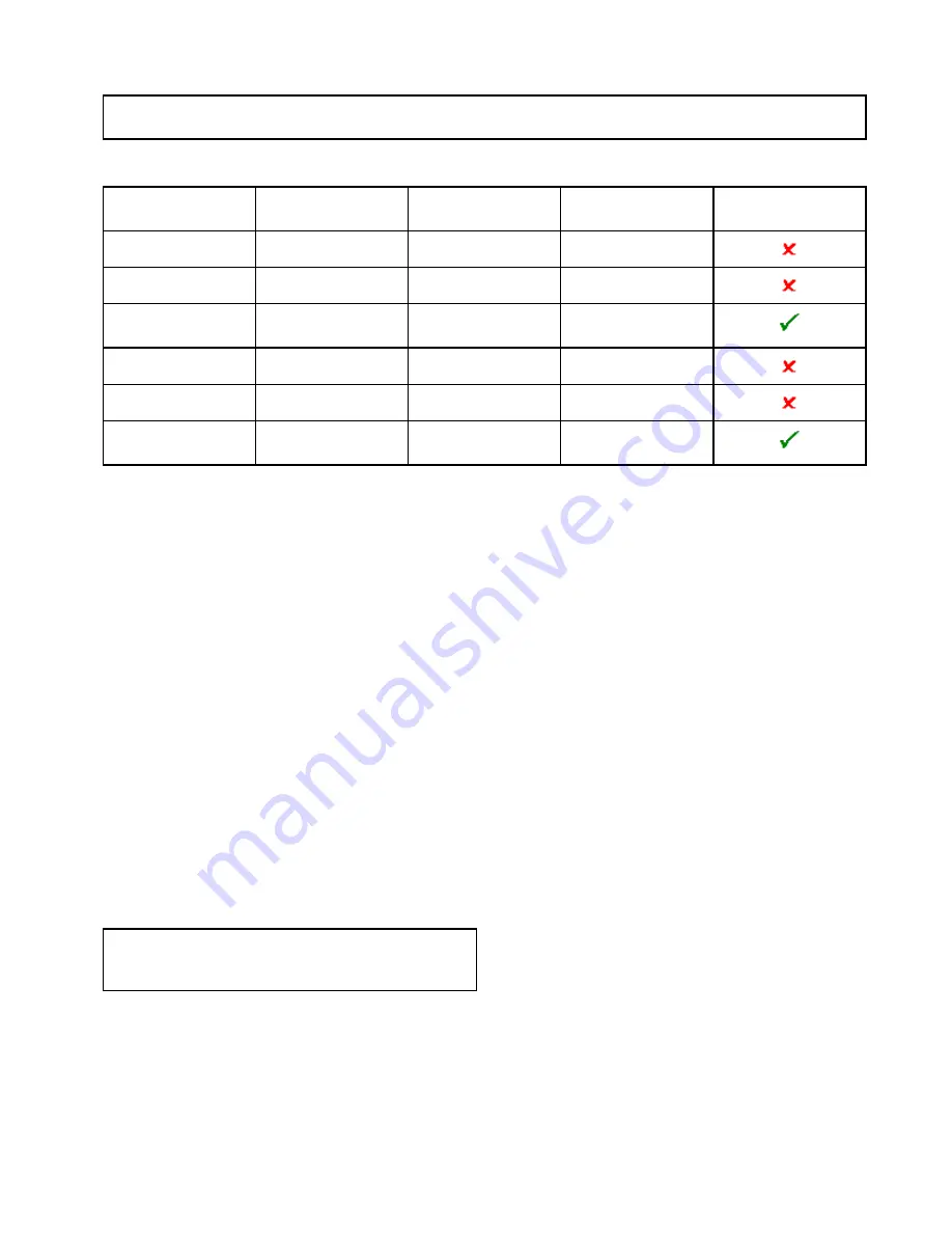
The following table details the different types of engine supported by the ECI interface unit, and the setup
requirements for each:
Engine CAN bus
protocol
Number of engines
Engine CAN bus
configuration
Number of ECI units
Setup via wizard on
MFD required
NMEA 2000
1
Single CAN bus
1
NMEA 2000
2+
Single shared CAN bus
1
NMEA 2000
2+
Separate CAN bus for
each engine
1 for each CAN bus
J1939
1
Single CAN bus
1
J1939
2+
Single shared CAN bus
1
J1939
2+
Separate CAN bus for
each engine
1 for each CAN bus
Engine interfacing without an ECI unit
For engines with a NMEA 2000 CAN bus it may
be possible to connect to a Raymarine MFD via a
SeaTalk
ng
system without the use of a Raymarine
ECI unit.
Refer to your engine dealer and also your local
Raymarine dealer for advice on any engine
instancing requirements and suitable connection
cables.
Using the engine identification wizard
If your engine data appears in the wrong order on the
engine data pages you can correct this by running
the engine identification wizard.
From the Homescreen:
1. Select
Set-up > System Settings > External
Devices > Engines Set-up
.
2. If required change the number of engines your
vessel has by selecting
Num. of Engines:
and
entering the correct number of engines.
You can select up to 5 engines.
3. Select
Identify engines
.
Important:
It is important that only one engine is
running at a time, to ensure that the system can
isolate the correct engine data message.
4. Follow the onscreen prompts to complete the
engine identification wizard.
The engines that will be included in the
identification wizard are determined by the
Number of engines set during step 2 above.
i.
Switch Off ALL vessel engines and select
Next
.
The wizard will run through all engines (max
of 5 as defined in step 2 above) from port to
starboard in sequence.
ii. Turn On the
port engine
and select
OK
.
The wizard will now listen for data and assign
the engine instance as the port engine.
iii. Turn On the
center port engine
and select
OK
.
The wizard will now listen for data and assign
the engine instance as the center port engine.
iv. Turn On the
center engine
and select
OK
.
The wizard will now listen for data and assign
the engine instance as the center engine.
v. Turn On the
center starboard engine
and
select
OK
.
The wizard will now listen for data and assign
the engine instance as the center starboard
engine.
vi. Turn On the
starboard engine
and select
OK
.
The wizard will now listen for data and assign
the engine instance as the starboard engine.
5. Select
OK
on the Identify Engines confirmation
dialog.
The engines will now appear in the correct location
on the engine data page.
Data application
293
Содержание Raymarine gS 195
Страница 2: ......
Страница 26: ...26 gS Series...
Страница 43: ...D 36 mm 1 4 in E 39 2 mm 1 5 in F 90 mm 3 5 in Planning the installation 43...
Страница 44: ...44 gS Series...
Страница 110: ...110 gS Series...
Страница 146: ...146 gS Series...
Страница 174: ...174 gS Series...
Страница 175: ...Chapter 13 Man Overboard MOB Chapter contents 13 1 Man overboard on page 176 Man Overboard MOB 175...
Страница 178: ...178 gS Series...
Страница 181: ...Chapter 15 Fuel manager Chapter contents 15 1 Fuel manager overview on page 182 Fuel manager 181...
Страница 196: ...196 gS Series...
Страница 218: ...218 gS Series...
Страница 328: ...328 gS Series...
Страница 362: ...362 gS Series...
Страница 411: ...Chapter 31 Technical specification Chapter contents 31 1 Technical specification on page 412 Technical specification 411...
Страница 418: ...418 gS Series...
Страница 438: ...438 gS Series...
Страница 439: ......
Страница 440: ...www raymarine com...


