EXPERT Standard Series User Manual
147
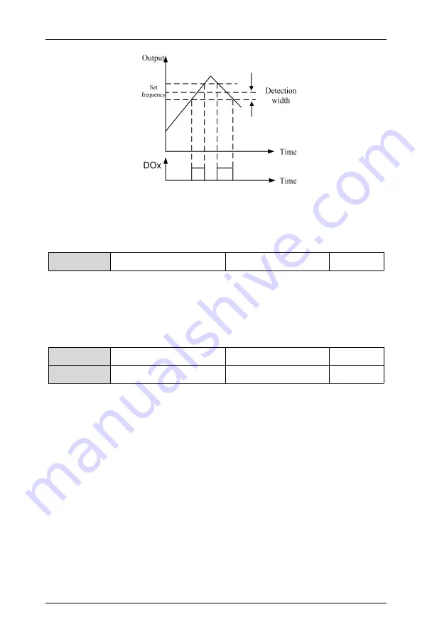
Figure 6-31 Frequency Arrival Signal Output Schematic Diagram
F6.20
DO2
maximum
output
pulse frequency
0~50.0kHz
10.0kHz
To define the maximum allowable output frequency of DO2 terminal, refer to the
description of F6.12.
Output range of DO2 pulse frequency: 0~maximum output pulse frequency.
F6.21
Counter reset value given
F6.22~9999
0
F6.22
Counter detection value
given
0~F6.21
0
The set count value given refers to the number of input pulses from DIx (count trigger
signal input function terminal), before the DOx (open collector output terminal) or the relay
outputs an indication signal.
As shown in Figure 6-31. When DIx inputs the 8th pulse, DO1 outputs an indication
signal. In this case, F6.21=8.
The specified count value given refers to the number of input pulses from DIx, before
the DOx or the relay outputs an indication signal, till the set count value is reached.
As shown in Figure 6-32. When DIx inputs the 5th pulse, DO2 starts to output an
indication signal. Till the set count value 8 is reached. In this case, F6.22=5. When the
specified count value is greater than the set count value, the specified count value is
invalid.


