EXPERT Standard Series User Manual
159
Note:
1. Given can also be the digital given and serial port given of the operation panel.
2. The two-phase input pulse helps to improve speed detection precision, and the
single-phase pulse input wiring is concise.
3. The two-phase pulse input can only adopt orthogonal mode.
4. If the drive te24 is used to supply power to the encoder, in this case, the
maximum load current of the optical encoder shall be ≤200mA.
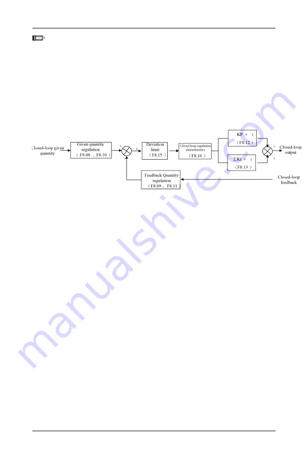
The working principle block diagram of the drive built-in PID is shown in Figure 6-38:
Figure 6-38 PI Principle Block Diagram
In the above figure, KP: Proportional gain; KI: Integral gain
In Figure 6-38, the definitions of closed-loop given quantity, feedback quantity,
deviation limit and proportional integral parameters are the same as the meanings of
ordinary PI adjustments, see the definitions in F8.01~F8.15.
The drive built-in PI has two characteristics as follows:
The relationship between the given quantity and the corresponding expected feedback
quantity is defined by F8.08~F8.11.
For example, in Figure 6-39, when the given quantity is an analog signal of 0~10 V, the
expected corresponding controlled quantity is 0~1 MPa, and the corresponding pressure
sensor signal is 4~20 mA. The relationship between the given quantity and the expected
feedback quantity is shown in Figure 6-39.


