EXPERT Standard Series User Manual
112
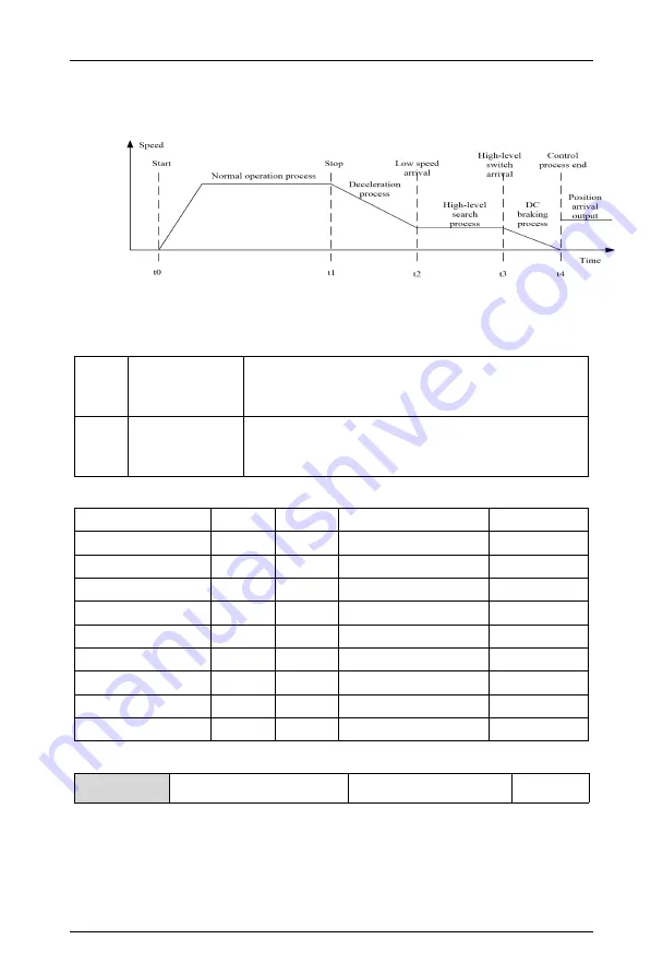
3: Positioning decelerate and stop
The working process is shown in the following Figure 6-12, and the specific control and
setting are as follows.
Terminal connection
DI1
Start button
When closed, the in-place output is disconnected first,
and then the forward rotation starts; when disconnected,
it switches to low speed operation.
DI4
In-place
photoelectric
switch
Stop signal, valid at rising edge.
Parameter setting
Function description
Functio
n code
Factory
value
Set range
Set value
Stop
and
brake
mode
F208
0
0~3
3
Start frequency of
stop and brake
F209
0
0~50.00Hz
2Hz
DC braking current
at stop
F211
0
0~100.0%
80%
Command mode
F101
0
0~2
1
Frequency source
selection
F102
0
0~5
1
DC braking time at
stop
F212
0~30.0s
2.0
Forward start
F600
0
0~63
36
In-place
photoelectric switch
F603
0
0~63
53
Overtime abnormal
stop
FC29
10.0
0~6553.6
10.0
4: Decelerate and stop (overpressure stall is invalid during deceleration)
F2.09
DC braking start frequency
at stop
0.00~60.00Hz
0.00Hz
Start frequency of stop DC braking: Refers to the switching point frequency when the
output frequency of the drive drops along the deceleration curve and suddenly drops to
zero during deceleration and stop. During the deceleration and stop process of the drive,
when the set frequency is less than the start frequency of stop DC braking, the output
frequency is zero.


