EXPERT Standard Series User Manual
103
Figure 6-2 Voltage and Frequency Schematic Diagram
Description:
1.
The maximum output frequency, upper limit frequency and lower limit
frequency shall be carefully set according to the nameplate parameters and the
operating status of the actually controlled motor.
2.
Except for restricted by the upper limit frequency and the lower limit frequency,
the output frequency of the drive during operating is also restricted by the starting
frequency, the starting frequency of the stop DC braking, the hopping frequency and
other parameter set values.
F1.11
Acceleration time 1
0.01~600.00
Model
determinati
on
F1.12
Deceleration time 1
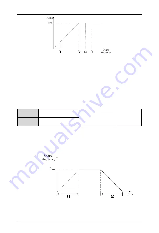
The acceleration time refers to the time required for the drive to accelerate from zero
frequency to the maximum output frequency, as shown in t1 in Figure 6-3. The deceleration
time refers to the time required for the drive to decelerate from the maximum output
frequency to zero frequency, as shown in t2 in the following figure.
Figure 6-3 Description of Acceleration Time and Deceleration Time Settings


