EXPERT Standard Series User Manual
120
V
max
V
b
f
Z
f
b
输出电压
输出频率
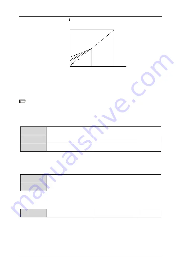
Vb: manuall torque boost voltage Vmax: Maximum output voltage
Fz: Cutoff frequency of torque boost fb: Basic operating frequency
Figure 6-16 Torque Boost Diagram
Note:
1. Improper setting of this parameter may cause motor heating or overcurrent
protection.
2. See function code F3.14 for the definition of fz.
F3.15
Torque boost gain 1
0 ~ 2.00 (higher than the
switching point)
0.20
F3.16
Torque boost integral time
1
0 ~ 10.00 (higher than
the switching point)
0.15
F3.17
Torque boost gain
switching frequency point
0.00~Rated power
15.00Hz
This function acts in VF mode, and is used to adjust the scale coefficient of torque
boost function. The larger this value, the larger the torque, but a too large value is easy to
cause oscillation, so do not change it generally.
This function acts in VF mode, and is to adjust the integral coefficient of torque boost
function. The larger this value, the larger the torque, but a too large value is easy to cause
oscillation.
F3.20
Automatic torque boost
limit
0.0~30.0%
10.0%
This function acts in VF mode, and is used to increase the low speed load carrying
capacity. When this parameter increases, the no-load current will increase, but a high
speed is easy to cause oscillation, so properly increase this parameter at a high speed but
without oscillation, and guarantee that the no-load current is less than 10% of the rated
current.
F3.18
Torque boost gain 2
0 ~ 2.00 (lower than the
switching point)
0.40
F3.19
Torque boost integral time
2
0 ~ 10.00 (lower than the
switching point)
0.30
Output frequency
Output voltage


