EXPERT Standard Series User Manual
132
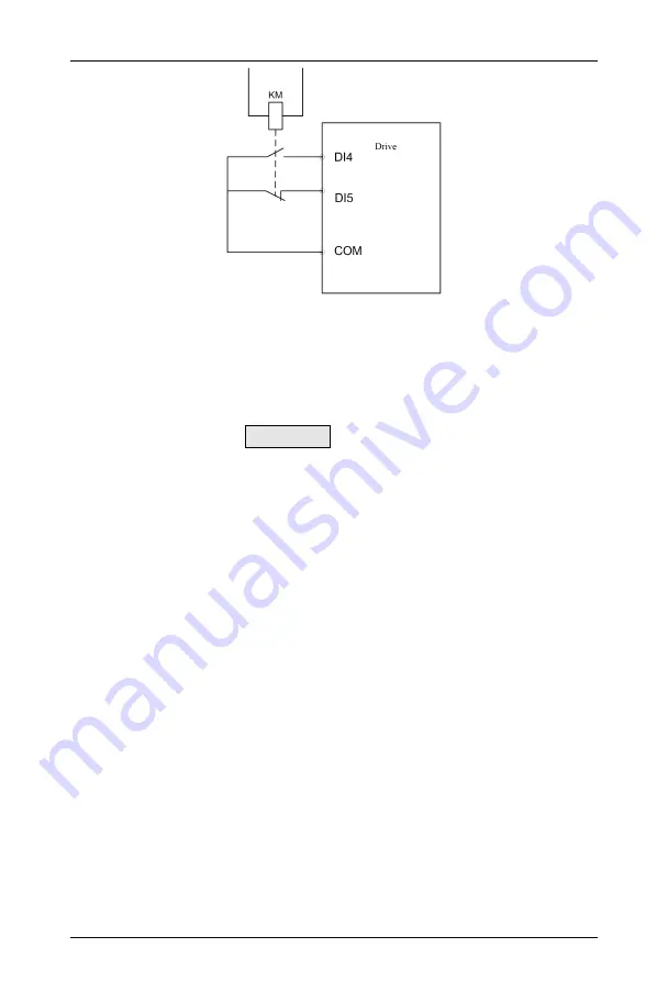
Figure 6-24 External Equipment Fault Normally on/Normally off Input
As shown in Figure 6-24, DI4 is a normally on input mode and DI5 is a normally off
input mode. Here, KM is an external equipment fault relay.
8: External reset input
When a fault alarm occurs in the drive, the fault can be reset through this terminal. Its
function is consistent with the STOP/RESET key function of the keyboard.
9 ~ 10: External jog operation control input JOGF/JOGR
Used to control jog operation in the terminal mode, JOGF is jog forward, and JOGR is
jog reversal, jog running frequency, jog interval time and jog acceleration/deceleration time
are defined in F2.20~F2.23.
11: Free stop input
This function has the same meaning as the free running stop defined in F2.08, but
here it is realized by control terminal, which is convenient for remote control.
12~13: Frequency increment instruction UP/decrement instruction DN
The frequency increase or decrease is realized through the control terminal, to perform
remote control replacing the operation panel. Valid when F1.02=1 under normal operation
or FC.25=2 as an auxiliary frequency. The increase/decrease rate is set by F6.10.
14: Simple PLC pause instruction:
Used to realize the pause control of the running PLC process. When this terminal is
valid, it runs at zero frequency. The PLC running is not counted; when invalid, the
automatic speed tracking starts, and PLC continues running. For usage, refer to the
function description of F9.00 and F9.08~F9.21.
15: Acceleration/deceleration prohibition instruction
Keep the motor from being affected by any external signal (except stop command),
maintain operating at the current speed.


