background image

Operating Modes

Parameter manual 

b maXX


BM3000

Document no.: 5.12001.07

Baumüller Nürnberg GmbH

610

of 820

4.8

deleted. Bit 12 „In position“ in 

Z

149.1

 spindle positioning status is a copy of bit 10 "Set 

value reached" in 

Z

108.3

 status word 1.

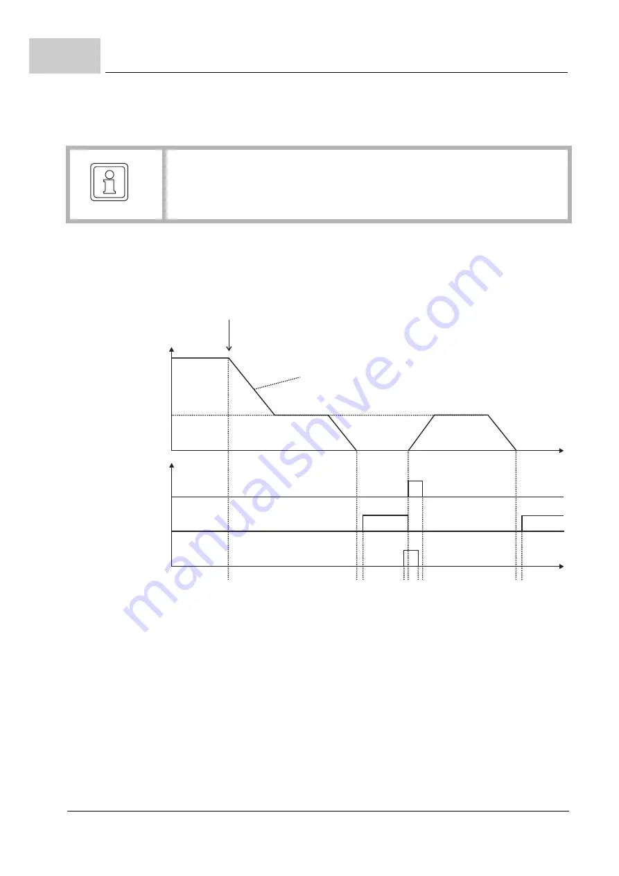
Operating sequence of a spindle positioning with a subsequent sequential 
positioning

Figure 205:

Spindle positioning with sequential positioning

Instant of time 1: Switching to operating mode spindle positioning; deceleration to spin-

dle positioning speed.

Instant of time 2: Position set value has reached active target position 

Z

149.10

.

Instant of time 3: Position actual value is in positioning window and positioning window 

time is up 

 Controller sets "set value reached". 

Instant of time 4: „Start sequential positioning“ is set.
Instant of time 5: Controller has recognized a start command, resets „set value reached“, 

sets the „Start-Command-Acknowledge“ and begins with sequential positioning.

Instant of time 6: „Start sequential positioning“ is deleted.
Instant of time 7: Controller deletes „Start-Command-Acknowledge“.
Instant of time 8: Position set value has reached active target position.
Instant of time 9: The position actual value is in positioning window and positioning win-

dow time is up 

 Controller sets "set value reached".

NOTE!

Bit 11 of the control word is only used for the sequential positioning. The first posi-
tioning after switching to operating mode spindle positioning is always executed im-
mediately independent of the status of bit 11!

t

n

1

2 3

4 5 67

8 9

Spindle
positioning speed

Status word Bit 12
„Start-Command-
Acknowledge“

Status word Bit 10
„Setpoint reached“

Control word Bit 11
„Start sequential
positioning“

Switched to

operating mode -6 spindle positioning

Slow down with spindle acceleration bipolar

Содержание b maXX BM2500

Страница 1: ...r manual Read the Operating Manual before starting any work Language English Translation Document No 5 12001 07 Part No 442290 Status 15 11 2017 b maXX BM3000 BM2500 Parameter manual Version 01 13 E 5 12001 07 ...

Страница 2: ...ou and inform us of your findings and comments so that they might be considered and possibly incorporated when the preliminary information becomes finalized reviewed by Baumüller The conditions noted in the following section under Liability do not apply in the case of pre liminary information Obligation This Parameter manual is a part of the device machine This Parameter manual must be ac cessible...

Страница 3: ...ltage test 47 3 3 Requirements for the electrical supply 47 3 4 Preparations 48 3 4 1 Communication via the service cable 51 3 4 2 Communication via EtherCAT 52 3 5 Switch on sequence 57 3 6 Performing the commissioning 58 4 Description of the Software Modules and Parameters 77 4 1 Cycle times of the software modules 77 4 2 Structure of the parameter overviews 78 4 3 System 80 4 3 1 System control...

Страница 4: ...der 166 4 4 6 3 Encoder optimization 166 4 4 6 4 Encoder correction 167 4 4 6 5 Encoder accuracy and excentricity 170 4 4 6 6 Resolver synchronization 171 4 4 6 7 Parameter overview 172 4 4 6 8 Description of the Parameters 174 4 4 7 Autotuning of Current controller 199 4 4 7 1 ProDrive Autotuning of the Current controller 200 4 4 7 2 Parameter overview 200 4 4 7 3 Description of the Parameters 20...

Страница 5: ... the Parameters 273 4 4 18 Master Slave Torque Coupling 280 4 4 18 1 Parameter overview 284 4 4 18 2 Description of the Parameters 285 4 4 19 Friction compensation 291 4 4 19 1 Description of the friction compensation 291 4 4 19 2 Identification of the friction torque curve 294 4 4 19 3 Parameter overview 294 4 4 19 4 Description of the Parameters 295 4 4 20 Synchronization 298 4 4 20 1 Parameter ...

Страница 6: ...386 4 5 4 2 Description of the Parameters 387 4 5 5 Signal Bus 391 4 5 5 1 Messages on the Signal Bus 391 4 5 5 2 Supply Ready for use 391 4 5 5 3 Chopper Resistor On 391 4 5 5 4 ProDrive Signal bus 392 4 5 5 5 Parameter overview 392 4 5 5 6 Description of the Parameters 392 4 5 6 Set Value Manager 394 4 5 6 1 Parameter overview 395 4 5 6 2 Description of the Parameters 395 4 6 Set Value Generator...

Страница 7: ...3 Reactive current brakes 490 4 7 3 4 Short circuit brake 491 4 7 3 5 Parameter Overview of the DC link controller 491 4 7 3 6 Description of the DC link controller parameter 492 4 7 4 Field weakening controller 494 4 7 4 1 Breakdown torque 498 4 7 4 2 Parameter overview 501 4 7 4 3 Description of the Field Weakening parameters 502 4 7 5 Two level controller 506 4 7 5 1 General 506 4 7 5 2 Two lev...

Страница 8: ... 2 13 Set Value Profiles 559 4 8 2 14 Comparison of Motion Profiles for Positioning 560 4 8 2 15 Control by Means of the Start Positioning Method 562 4 8 2 16 Parameter overview 566 4 8 2 17 Description of the Parameters 567 4 8 3 Operating mode Homing 583 4 8 3 1 Procedure of a homing under consideration of Zero pulse or Zero angle 583 4 8 3 2 Shifting the zero angle 584 4 8 3 3 Maximum distance ...

Страница 9: ...ng 648 4 8 10 4 Motor diagnosis 648 4 8 10 5 Parameter overview 649 4 8 10 6 Description of the Parameters 650 4 8 11 Sensorless control for asynchronous motors open loop 655 4 8 11 1 Sensorless control 655 4 8 11 2 Catch on Fly 656 4 8 11 3 Parameter overview 657 4 8 11 4 Description of the Parameters 658 4 8 12 Operating Mode U f Characteristic 660 4 8 12 1 Compensating controller for accelerati...

Страница 10: ... 4 11 2 2 Description of the Parameters 720 4 11 3 Overload monitoring of the power unit 723 4 11 3 1 Ixt model 723 4 11 3 2 Temperature model 727 4 11 3 3 Real power limit 730 4 11 4 Temperature monitoring of the motor 731 4 11 5 Overload monitoring of the motor I2 t 731 4 11 5 1 General information 731 4 11 5 2 Speed variable l2 t overload monitoring 735 4 11 5 3 Monitoring of the single phases ...

Страница 11: ... to the area of application of the device must be observed Before starting any work on the device completely read through the Operating Manual in particular the chapter on safety information The Operating Manual is an integral part of the product and must be kept in the immediate vicinity of the device in order to be ac cessible to personnel at all times The Parameter Manual provides information a...

Страница 12: ... injury and damage to property Recommenda tions DANGER warns of an imminently dangerous situation which will result in death or serious in jury if not avoided WARNING warns of a potentially dangerous situation which may result in death or serious in jury if not avoided CAUTION warns of a potentially dangerous situation which may result in minor or slight injury if not avoided NOTICE warns of a pot...

Страница 13: ... out the assembly or installation is liable for damage arising during assembly or upon connection 1 4 Copyright Treat the Parameter Manual confidentially It is intended exclusively for persons involved with the device It must not be made available to third parties without the written permis sion of the manufacturer NOTE The details text drawings pictures and other illustrations contained within ar...

Страница 14: ...ices in installed positions that are not shown here is not permissible and must be checked with the factory in each individual case If the devices are operated differently than described here any guarantee will be invalidated 1 7 Customer service Our customer service department is available for technical information Information concerning the responsible contact person can be obtained at any time ...

Страница 15: ...tioning prop erly This commissioning does not constitute a complete set up of the device for your applica tion Before the commissioning make sure that the technical requirements are met 1 All points including the installation in the b maXX 2500 Operating Manual 5 16020 have been followed 2 Check of the requirements for the electrical supply 3 Check of the requirements for the electrical cables and...

Страница 16: ...or instruction or authorization to commission ground and characterize power circuits and devices in accordance with safety engineering standards m Training or instruction in accordance with safety engineering standards in the care and use of appropriate safety equipment WARNING Danger due to incorrect installation and initial commissioning Installation and initial commissioning require qualified p...

Страница 17: ...l injury DANGER Risk of fatal injury from electrical current During the routine test of these devices a voltage test is performed by Baumüller Nürnberg GmbH in accordance with EN 61800 5 1 Section 5 2 3 2 It is thus unnec essary for the customer to do this Therefore m Subsequent tests of the devices using high voltages may only be performed by Baumüller Nürnberg GmbH m Disconnect the converter fro...

Страница 18: ...o that you can perform the com missioning efficiently it is advantageous to have all the data at hand for the commis sioning Data for Baumüller motors are available in the form of a Motor Database within the operating software 4 Make sure that all the necessary data are at hand Motor data Identification plate These data can be found e g on the identification plate for the motor that you are using ...

Страница 19: ...active 7 Make sure that all safety devices are connected on the supply and motor sides and are ready for operation 8 Make sure that the encoder for motor control sine cosine encoder is connected to the encoder evaluation module with the appropriate encoder cable 9 Make sure that the PC Laptop is connected to the controller Name Value e g Used for entering in the parameter list parame ter Max curre...

Страница 20: ...g Framework ProMaster n Leave the base address on the EtherCAT Master unchanged 192 168 1 1 h Set the desired IP address on the BM2500 controller here 192 168 1 2 You will find further information about this in the b maXX BM2500 5 16020 Operating Manual Art No 441838 and in the EtherCAT 5 10030 Application Manual Art No 440084 h Set a fixed IP address on the PC or use a second network card System ...

Страница 21: ...500 Drive from the catalog n Open activate the Workspace window n Click the Controller PLC in ProMaster n Click EtherCAT Master Configure Master Bus ProEtherCAT in the Workspace win dow n The window will open Figure 2 ProEtherCAT n Click on Connect n Select the tab Download Update list Download Figure 3 ProEtherCAT Download n Click on Close n Select the tab Bus control click on Operational ...

Страница 22: ...ual b maXX BM3000 Document no 5 12001 07 Baumüller Nürnberg GmbH 22 of 820 2 5 n Start ProDrive and select Find device Figure 4 ProDrive Find device n The PLC will appear here with 192 168 1 1 and the controller with 192 168 1 2 n Click on OK ...

Страница 23: ...t the device Button SELECT DEVICE n Select the device type for which parameters are to be set Button TYPE here b maXX 2500 Drive n Select the communication Button TYPE here TCP IP Figure 5 ProDrive Device select with EtherCAT communication 10 Start the graphical user interface by clicking on OK ...

Страница 24: ...12001 07 Baumüller Nürnberg GmbH 24 of 820 2 5 11 Wait until the ProDrive start window appears Figure 6 ProDrive Start window 12 Then press Connect 13 This concludes the preparations The remainder of the commissioning is described in ZPerforming the commissioning on page 26 ...

Страница 25: ... no 5 12001 07 25 of 820 2 2 6 Switch on sequence The following overview shows the commissioning schematically You will find the individ ual steps of the commissioning described in detail in ZPerforming the commissioning from page 26 Figure 7 Switch on sequence ...

Страница 26: ...tarts up 2 Establish communication as described in ZPreparations on page 18 3 Start the ProDrive program if it is not already running 4 Then click on auf Drive Manager in ProDrive Figure 8 ProDrive Navigation Drive manager Acknowledging warnings errors 5 Acknowledge any warnings errors that may be present in the Drive manager win dow press the Reset errors button several times if necessary NOTE An...

Страница 27: ...al b maXX BM3000 Document no 5 12001 07 27 of 820 2 Figure 9 ProDrive Drive Manager NOTE Due to the numerous possible combinations of motors and encoders it is only possi ble to give an example here Enter your own motor and encoder data ...

Страница 28: ...Performing the commissioning Parameter manual b maXX BM3000 Document no 5 12001 07 Baumüller Nürnberg GmbH 28 of 820 2 7 6 Click on Power unit Figure 10 ProDrive Navigation for Power unit ...

Страница 29: ...12001 07 29 of 820 2 7 In the Maximum drive current box enter the current required for your application at most the limiting current of the motor according to the data sheet 1 5 A at which you wish to operate the motor and the power unit Figure 11 ProDrive Power unit ...

Страница 30: ...no 5 12001 07 Baumüller Nürnberg GmbH 30 of 820 2 7 Setting encoder parameters The parameters for the encoder still have to be entered 8 Go back to the navigation 9 Click on Scaling Figure 12 ProDrive Navigation Scaling The Scaling window opens Figure 13 ProDrive Scaling ...

Страница 31: ...Commissioning BM25xx Parameter manual b maXX BM3000 Document no 5 12001 07 31 of 820 2 10 Click on at speed 11 Go back to the navigation 12 Click on Encoder 1 Figure 14 ProDrive Navigation Encoder ...

Страница 32: ...ACE interface With a sine cosine encoder with a HIPERFACE interface the data are transferred auto matically over the HIPERFACE interface do not alter the data m Sine cosine without HIPERFACE e g Number of Pulses 512 m Sine cosine without HIPERFACE e g Revolutions 1 14 Enter the overspeed limit manually in the parameter list in the diagnostic block FB 006 Parameter number 006 005 and 006 007 enter ...

Страница 33: ... of 820 2 15 Change back to the navigation and click on Motor general Figure 16 ProDrive Navigation Motor general Using the motor database 16 Click on the Motor database button in the icon bar in the Motor window Figure 17 ProDrive Motor database 17 The following window appears ...

Страница 34: ...database to the corresponding parameters and display fields 20 Check all the values for the motor using the motor data sheets This is only for check ing purposes if you are using the Baumüller motor database If you are employing mo tors from third party manufacturers you must do this in any case NOTE The values for nominal speed and maximum speed are the same for synchronous motors and are thus ad...

Страница 35: ... you will not find any discrepancies between the motor data sheet and the data taken automatically from the database 21 Click on Motor in the navigation Checking motor data 22 You will find all the important motor data or parameters displayed in the Motor window and the Synchronous Motor sub window Check all data Figure 19 ProDrive Motor general ...

Страница 36: ... 7 Figure 20 ProDrive Motor synchronous Using the parame ter list If you are not using the Baumüller motor database you can also enter all the motor pa rameters using the Parameter list 23 Click on the Parameter list in the navigation 24 In the parameter list click on Motor Id Figure 21 ProDrive Parameterlist Motor Id ...

Страница 37: ...mum speed mechanical m Number of pole pairs Z107 19 Pole pairs m Phase sequence Z107 38 Motor flags Bit 0 0 counter clockwise Bit 0 1 clock wise Now save the entered data 25 Click on Parameter set management in the navigation Figure 22 ProDrive Navigation Dataset management 26 Click on the Save all button in the Dataset management Figure 23 ProDrive Dataset management ...

Страница 38: ...s to the b maXX main power supply control voltage By switching off and on again you can check whether the settings you have made will result in warnings or errors No errors may be present Autotuning of the current controller Now perform the autotuning of the current controller 31 Go to the navigation and click on Configuration then click on Autotuning Current controller Figure 24 ProDrive Navigati...

Страница 39: ...Commissioning BM25xx Parameter manual b maXX BM3000 Document no 5 12001 07 39 of 820 2 Figure 25 ProDrive Autotuning Current controller ...

Страница 40: ...ered device It was carried out already Please check whether the measured value corresponds to the expected value With Baumüller motors resolver 330 5 sine cosine 240 5 If the values do not correspond to the expected values please proceed as follows 35 Go to the navigation and click on Operating modes then click on Find notch posi tion Figure 26 ProDrive Navigation Find notch position 36 Click on t...

Страница 41: ...ocument no 5 12001 07 41 of 820 2 The Drive Manager window will also appear Figure 27 ProDrive Find notch position Drive manager 37 For the method select fix current angle and rotating shaft 38 Select Find notch position in the Drive Manager Axis 1 window ...

Страница 42: ...motor rotate briefly Initial rotation of the motor 45 Go back to the navigation 46 Click on Set value generators 47 Click on Ramp function generator Figure 28 ProDrive Navigation Ramp function generator WARNING Risk of injury due to moving components Rotating and or linearly moving components can cause serious injuries If the motor is not rotating freely the motor and parts connected to it may be ...

Страница 43: ...ment no 5 12001 07 43 of 820 2 Figure 29 ProDrive Ramp function generator 48 Enter values in the following input fields m Ramp function generator Input h Enter the value 10 Confirm with Enter 49 Open the Drive manager dialog Figure 30 ProDrive Drive manager ...

Страница 44: ...og 55 The motor will then stop 56 Switch the pulse enabling off Saving the data set This data set should now be saved 57 Click on the Dataset management icon in the icon bar 58 Click on the Save All button in the Dataset management Figure 31 ProDrive Dataset management 59 Wait until OK is displayed under Data Set State At this point the data set is saved in Flash memory Switching off the drive To ...

Страница 45: ...his commissioning does not constitute a complete set up of the device for your applica tion Before the commissioning make sure that the technical requirements are met 1 All points including the installation in the b maXX 3000 Operating Manual 5 11018 have been followed 2 Check of the requirements for the electrical supply 3 Check of the requirements for the electrical cables and provision of appro...

Страница 46: ... are able to recognize and avoid potential dangers The qualifications re quired for working on the unit are for example m Training or instruction or authorization to commission ground and characterize power circuits and devices in accordance with safety engineering standards m Training or instruction in accordance with safety engineering standards in the care and use of appropriate safety equipmen...

Страница 47: ...rtain parts of the unit are of necessity at a haz ardous voltage Therefore m Pay attention to the areas on the device that could be dangerous during the elec trical installation Figure 32 Danger areas during electrical installation 3300_0009 cdr _rev01_int DANGER Risk of fatal injury from electrical current During the routine test of these devices a voltage test is performed by Baumüller Nürnberg ...

Страница 48: ...cular that all safety regulations have been observed see Assembly in the Operating Manual for the b maXX 3000 basic unit 2 Make sure that the installation is carried out correctly and in particular that all safety regulations have been observed see Installation in the Operating Manual for the b maXX 3000 basic unit DANGER Danger to life from electric current If the requirements for the electrical ...

Страница 49: ... can among other things enter motor and encoder data in the operating software or correct incorrect values So that you can perform the com missioning efficiently it is advantageous to have all the data at hand for the commis sioning Data for Baumüller motors are available in the form of a Motor Database within the operating software 4 Make sure that all the necessary data are at hand ...

Страница 50: ... patch panel and are functioning Make sure that the switch is in the rest position inactive Name Value e g Used for entering in the parameter list parame ter Motor type designation DS 56 M Parameter list Motor configuration Z107 2 Motor type Nominal voltage UN 330 V Parameter list Motor configuration Z107 8 Motor nominal voltage Nominal current IN 4 0 A Parameter list Motor configuration Z107 9 Mo...

Страница 51: ...e sure that the PC Laptop is connected to the controller 3 4 1 Communication via the service cable The service interface transmits controller parameters from a PC laptop to the controller via the parameterizing software ProDrive h Connect free USB port of the PC laptop with the controller The driver connection was installed on the PC laptop with ProDrive already The settings of the connection baud...

Страница 52: ...the EtherCAT Master unchanged 192 168 1 1 n Set the desired IP address on the BM3000 controller here 192 168 1 2 You will find further information about this in the b maXX BM3000 5 11018 Operating Manual Art No 441839 n Set a fixed IP address on the PC or use a second network card System Control Network Connections LAN Connection Properties Internet Protocol TCP IP Properties Assign fixed IP addre...

Страница 53: ...r PLC in ProMaster n Click EtherCAT Master Configure Master Bus ProEtherCAT in the Workspace win dow n The window will open Figure 35 ProEtherCAT n Click on Connect n Select the tab Download Update list Download Figure 36 ProEtherCAT Download n Click on Close n Select the tab Bus control click on Operational ...

Страница 54: ...XX BM3000 Document no 5 12001 07 Baumüller Nürnberg GmbH 54 of 820 3 4 n Start ProDrive and select Find device Figure 37 ProDrive Find device n The PLC will appear here with 192 168 1 1 and the controller with 192 168 1 2 n Click on OK ...

Страница 55: ...evice Button SELECT DEVICE n Select the device type for which parameters are to be set Button TYPE here bmaXX52_TwoAxis_EtherCAT_Slave n Select the communication Button TYPE here TCP IP Figure 38 ProDrive Device select with EtherCAT communication 10 Start the graphical user interface by clicking on OK ...

Страница 56: ... Baumüller Nürnberg GmbH 56 of 820 3 4 11 Wait until the ProDrive start window appears Figure 39 ProDrive Start window 12 Then press Connect 13 This concludes the preparations The remainder of the commissioning is described in ZPerforming the commissioning on page 58 ...

Страница 57: ... no 5 12001 07 57 of 820 3 3 5 Switch on sequence The following overview shows the commissioning schematically You will find the individ ual steps of the commissioning described in detail in ZPerforming the commissioning from page 58 Figure 40 Switch on sequence ...

Страница 58: ...ide this im mediately with the pulse enable switching element m LED H13 a red LED means that the current limit has been reached Reduce the loading on the motor Continue with the parameter setting m LED H14 a red LED indicates a error condition Rectify the error later using the ProDrive operating program Continue with the parameter setting 2 Establish communication as described in ZPreparations on ...

Страница 59: ...al b maXX BM3000 Document no 5 12001 07 59 of 820 3 Figure 42 ProDrive Drive Manager NOTE Due to the numerous possible combinations of motors and encoders it is only possi ble to give an example here Enter your own motor and encoder data ...

Страница 60: ... GmbH 60 of 820 3 6 6 Click on Power unit Figure 43 ProDrive Navigation for Power unit 7 In the Maximum drive current box enter the current required for your application at most the limiting current of the motor according to the data sheet 2 5 A at which you wish to operate the motor and the power unit ...

Страница 61: ...Commissioning BM3xxx Parameter manual b maXX BM3000 Document no 5 12001 07 61 of 820 3 Figure 44 ProDrive Power unit ...

Страница 62: ...07 Baumüller Nürnberg GmbH 62 of 820 3 6 Setting encoder parameters The parameters for the encoder still have to be entered 8 Go back to the navigation 9 Click on Scaling Figure 45 ProDrive Navigation Scaling The Scaling window opens Figure 46 ProDrive Scaling 10 Click on at speed ...

Страница 63: ...Commissioning BM3xxx Parameter manual b maXX BM3000 Document no 5 12001 07 63 of 820 3 11 Go back to the navigation 12 Click on Encoder 1 Figure 47 ProDrive Navigation Encoder ...

Страница 64: ...ACE interface With a sine cosine encoder with a HIPERFACE interface the data are transferred auto matically over the HIPERFACE interface do not alter the data m Sine cosine without HIPERFACE e g Number of Pulses 512 m Sine cosine without HIPERFACE e g Revolutions 1 14 Enter the overspeed limit manually in the parameter list in the diagnostic block FB 006 Parameter number 006 005 and 006 007 enter ...

Страница 65: ... of 820 3 15 Change back to the navigation and click on Motor general Figure 49 ProDrive Navigation Motor general Using the motor database 16 Click on the Motor database button in the icon bar in the Motor window Figure 50 ProDrive Motor database 17 The following window appears ...

Страница 66: ...e motor data sheets This is only for check ing purposes if you are using the Baumüller motor database If you are employing mo tors from third party manufacturers you must do this in any case Altering motor data When using the Baumüller motor database you will not find any discrepancies between the motor data sheet and the data taken automatically from the database 21 Click on Motor in the navigati...

Страница 67: ...maXX BM3000 Document no 5 12001 07 67 of 820 3 Checking motor data 22 You will find all the important motor data or parameters displayed in the Motor window and the Synchronous Motor sub window Check all data Figure 52 ProDrive Motor general ...

Страница 68: ... are not using the Baumüller motor database you can also enter all the motor pa rameters using the Parameter list 23 Click on the Parameter list in the navigation 24 In der parameter list click on Motor Id Figure 54 ProDrive Parameterlist Motor Id The following motor parameters must be specified m Maximum speed mech Z107 26 Maximum speed mechanical m Number of pole pairs Z107 19 Pole pairs ...

Страница 69: ... the navigation Figure 55 ProDrive Navigation Dataset management 26 Click on the Save All button in the Dataset management Figure 56 ProDrive Dataset management 27 Wait until Successful is displayed under Data Set Status 28 At this point the data set is saved in Flash memory 29 Disconnect the device from the main power and control voltage supplies 30 Reconnect the power supplies to the b maXX main...

Страница 70: ...result in warnings or errors No errors may be present Autotuning of the current controller Now perform the autotuning of the current controller 31 Go to the navigation and click on Configuration then click on Autotuning Current controller Figure 57 ProDrive Navigation Autotuning Current controller 32 Activate pulse enable 33 Click on Start 34 Wait until Self optimization completed appears in field...

Страница 71: ...cument no 5 12001 07 71 of 820 3 Figure 58 ProDrive Autotuning Current controller Searching for the notch position It is now necessary to search for the notch position 35 Go to the navigation and click on Operating Modes then click on Find Notch Posi tion ...

Страница 72: ...rforming the commissioning Parameter manual b maXX BM3000 Document no 5 12001 07 Baumüller Nürnberg GmbH 72 of 820 3 6 Figure 59 ProDrive Navigation Find notch position 36 Click on the Drive Manager icon ...

Страница 73: ...Document no 5 12001 07 73 of 820 3 The Drive Manager window will also appear Figure 60 ProDrive Rastlage suchen Antriebsmanager 37 For the method select fix currentangle and rotating shaft 38 Select Find notch position in the Drive Manager Axis 1 window ...

Страница 74: ...motor rotate briefly Initial rotation of the motor 45 Go back to the navigation 46 Click on Set value generators 47 Click on Ramp function generator Figure 61 ProDrive Navigation Ramp function generator WARNING Risk of injury due to moving components Rotating and or linearly moving components can cause serious injuries If the motor is not rotating freely the motor and parts connected to it may be ...

Страница 75: ...ment no 5 12001 07 75 of 820 3 Figure 62 ProDrive Ramp function generator 48 Enter values in the following input fields m Ramp function generator Input h Enter the value 10 Confirm with Enter 49 Open the Drive manager dialog Figure 63 ProDrive Drive manager ...

Страница 76: ...og 55 The motor will then stop 56 Switch the pulse enabling off Saving the data set This data set should now be saved 57 Click on the Dataset management icon in the icon bar 58 Click on the Save All button in the Dataset management Figure 64 ProDrive Dataset management 59 Wait until OK is displayed under Data Set State At this point the data set is saved in Flash memory Switching off the drive To ...

Страница 77: ...130 15 effective cycle time readable in Z47 65 Speed controller posi tion controller 62 5 µs to 1000 µs adjustable in RT0 Cycle time Z1 8 Two level controller 1 ms Operation modes of the task RT1 1 ms Operation modes of the fieldbus task Adjustable in fieldbus cycle time Z131 18 and division ratio fieldbus task Z131 20 Cam generator Adjustable in fieldbus cycle time Z131 18 and division ratio fiel...

Страница 78: ...ble from 62 5 µs to 100 s Z109 1 Operation mode Task 12 Coupled operation Fieldbus 7 Autotuning Remaining time manage ment 6 Spindle positioning RT1 5 Synchronous operation with virtual master axis RT1 Synchronous operation with real master axis RT0 set value RT1 Management 4 Position control with synchronous set of set points Fieldbus 3 Speed control with ramp function generator RT1 default setti...

Страница 79: ...actor between display ProDrive and internal standardization X in column Read only Parameter is read only X in column Storage Parameter will be stored in Flash X in column DS support Parameter will be stored in data sets of the Flash X in column Cyclic Write Parameter may be written cyclic e g using process data of the fieldbus Example Number Z110 5 Functional block ramp function generator paramete...

Страница 80: ...type UDINT 0 5 0 1 1 X 10² 4 Firmware build number UDINT 0 0xFFFFFFFF 0 1 1 X 10² 5 Firmware name STRING 1 1 X 10² 6 Firmware version information STRING 1 1 X 10² 7 Firmware time stamp STRING 1 1 X 10² 8 Bootloader0 version STRING 1 1 X 10² 9 Bootloader1 version STRING 1 1 X 10² 10 Fpga Id UDINT 0 0xFFFFFFFF 0 1 1 X 10² 11 Bootloader flags UDINT 0 0xFFFFFFFF 0 1 1 X 10² 13 Expected system Fpga Id ...

Страница 81: ...1 X 102 25 Hardware board identification STRING 1 1 102 26 Circuit board assembly STRING 1 1 102 28 Hardware date STRING 1 1 102 30 Controller serial number UDINT 0 0xFFFFFFFF 0 1 1 102 31 Controller article number UDINT 0 0xFFFFFFFF 0 1 1 102 32 Device serial number UDINT 0 0xFFFFFFFF 0 1 1 102 33 Device article number UDINT 0 0xFFFFFFFF 0 1 1 102 35 Device type Code STRING 1 1 139 1 Password UIN...

Страница 82: ...ed which inhibits enabling of the drive 1 10 Task fieldbus cycle time The parameter displays the cycle time for the task fieldbus The task fieldbus cycle time must not fall below the RT0 Cycle time In this case the task fieldbus cycle time is limited to the RT0 Cycle time the error 505 will be triggered and thus the enabling of the drive will be inhibited 102 1 Firmware number Internal Baumüller f...

Страница 83: ...Internal build number 102 5 Firmware name Firmware term 102 6 Firmware version information Summarized text information of the firmware version 102 7 Firmware time stamp Time stamp for the firmware generation 102 8 Bootloader0 version Version of Bootloader 0 102 9 Bootloader1 version Version of Bootloader 1 102 10 Fpga version Version of the FPGA ...

Страница 84: ...are number Baumüller internal fieldbus firmware number Bit Meaning 0 Current BL1 was faulty fallback used 1 Current firmware was faulty fallback used 2 Current FPGA was faulty fallback used 3 Current communication firmware was faulty fallback used 4 New BL1 file has been saved in Flash 5 New firmware file has been saved in Flash 6 New FPGA file has been saved in Flash 7 New communication firmware ...

Страница 85: ...er firmware version time stamp 102 21 Fieldbus controller firmware type Firmware type 0 Production 1 Beta 2 Prototype 102 22 Fieldbus controller firmware build number Number for counting beta states prototypes or even nightly builds 102 23 Board data command Command 3 is provided with a key Value Command Meaning 0 No command or STOP command 1 Write current data set from the parameters to the seria...

Страница 86: ... development NN Sequential number BB Assembly variant AA Revision number D1 Technical status Format of HW board identifier 16 byte string e g 33 0707B i e format 33 JJ NN AA 102 26 Circuit board assembly Format 16 byte string e g 01 Safe 102 28 Hardware date Format 16 byte string e g 01 04 2009 102 30 Controller serial number Serial number of the controller PCB as a 32 bit numerical value Value Me...

Страница 87: ...XXXX XXXXX X XXXXX S0X XX XX EXX XX 139 1 Password Password for protecting access to system parameters The value displayed corresponds to the password level 139 2 Baudrate Baud rate for serial communication Valid baud rates 9600 19200 38400 57600 115200 230400 460800 921600 Baud Each time the controller is switched on the baud rate is set to 38400 NOTE The controller has several possible interface...

Страница 88: ...al time tasks 158 2 Real time load average Average value of the computing time load by the real time tasks The parameter is re freshed every second and shows the mean computing time load since the last update 158 3 Max real time load Maximum value of the computing time load by the real time tasks The parameter can be reset by writing a value 158 4 Interrupt load Computing time load by the interrup...

Страница 89: ...e Modules and Parameters Parameter manual b maXX BM3000 Document no 5 12001 07 89 of 820 4 158 6 Interrupt load max Maximum value of the computing time load by the interrupt routine The parameter can be reset by writing a value ...

Страница 90: ... display UDINT 0 0xFFFFFFFF 0x1010000 1 1 X Bit Value Meaning 15 0 Reserved 23 16 0 Only errors with a response set in the parameters are displayed the error LED H14 axis 1 or H24 axis 2 is on in case of error If only warnings or errors without a response set in the parameters are triggered the error LED flashes 1 All errors and warnings are displayed the error LED is on perma nently in case of er...

Страница 91: ...s possibly not fast enough for specific applications Therefore a mains failure detection is optionally possible via the DC link volt age see Z130 35 Behavior at mains failure The drive can be configured that operation is possible at a mains failure for a set time Z130 25 Different kinds of behavior can be set see Z130 10 Disable only motor operation generator operation is enabled field current is ...

Страница 92: ...s 19 6 and 107 9 see ZMotor from page 111 For Parameters 175 1 175 2 and 175 15 see ZDiagnosis from page 690 Number Name Type Min Max Default Value Unit Factor Read only Storage DS Support Cyclic Write 129 3 Hardware id STRING 1 1 129 4 Hardware name STRING 1 1 129 5 Current scaling gain FLOAT 0 10000 1 1862 1 1 129 6 DC scaling gain FLOAT 0 10000 1 03885 1 1 129 7 Main voltage scaling gain FLOAT ...

Страница 93: ...T 10 1000 0 10 0 V 1 1 129 49 Amp article number UDINT 0 0xFFFFFFFF 0 1 1 129 50 Chopper resistance FLOAT 0 0xFFFFFFFF 100 Ohm 1 1 129 51 Chopper peak power FLOAT 0 0xFFFFFFFF 1200 W 1 1 129 52 Chopper PT1 model gain FLOAT 0 0xFFFFFFFF 1 4 1 1 129 53 Chopper PT1 model time constant FLOAT 0 0xFFFFFFFF 7 5 1 1 129 55 Chopper maximum tempera ture FLOAT 0 0xFFFFFFFF 180 C 1 1 129 85 Charging blocking ...

Страница 94: ...s fail ure FLOAT 10 1000 450 V 1 1 X 130 38 Udc hysteresis for mains fail ure FLOAT 10 500 50 V 1 1 X 130 39 Udc autodetect FLOAT 0 1000 0 V 1 1 X 130 41 Actual PWM frequency UINT 2 16 8 kHz 1 1 X 175 3 Max device control cabin temperature UINT 0 55 40 Grad C 1 1 X 175 4 Max device altitude UINT 0 5000 1000 m 1 1 X 175 5 Max device mains voltage UINT 0 530 400 V 1 1 X 175 6 Max device DC link volt...

Страница 95: ...y settings for the configuration 129 9 IGBT dead time Dead time for the power unit transistors 129 10 Min pulse suppression Minimum pulse suppression is used to prevent extremely short duty cycles for pulse width modulation such as may occur when outputting large voltages Instead of generating ex tremely short On Off switching pulses the switching state of the IGBTs is extended to the next PWM per...

Страница 96: ...he analog current filter 129 12 Nominal current 2 kHz 129 13 Nominal current 4 kHz 129 14 Nominal current 8 kHz 129 15 Nominal current 16 kHz Nominal current of converter at the corresponding PWM switching frequency Z130 15 The value in this parameter applies to the required operating conditions See chapter Technical data of the device s operating manual The instantaneous nominal current of the po...

Страница 97: ...ependent of the entered PWM frequency Z130 15 is dis played in the parameter Z6 25 The value of the peak current Z129 16 to Z129 19 or parameter Z6 25 corre sponds to the maximum current by which the device may be operated at peak current pro cessing time Z129 22 corresponding to the specifications in chapter Technical data of the device s operating manual 129 20 Overcurrent threshold Monitoring t...

Страница 98: ...arameter Z130 10 is not set Maximum current at which the drive can be operated with a phase failure 129 26 Max heat sink temperature Switch off threshold for heat sink temperature 129 27 Max interior temperature Switch off threshold for the internal temperature of the power unit 129 41 Max ground current Monitoring the maximum ground current 129 42 Min DC link voltage Monitoring the minimum DC Lin...

Страница 99: ...l state Z175 2 Bit 0 The value in this parameter is valid for the required operating requirements See chapter Technical data in the Instruction Handbook The currently valid power unit peak current dependent of the entered PWM frequency Z130 15 is shown in parameter Z6 25 There is no connection between the peak current 129 85 to 129 88 and the peak current time Z129 22 The maximum permitted time fo...

Страница 100: ... 0 Limitation of the motor current to Z129 25 Current phase error no shutdown 1 Limitation of the motor current to Z107 9 Nominal current shutdown of the drive after the duration in Z130 24 Phase error delay time 3 Reserved 4 0 Three phase supply to X202 1 Single phase supply to X202 If this bit is set the message 1047 Warning Phase Failure is sup pressed Bit 2 may not be set at the same time 5 Au...

Страница 101: ...If the phase error is cleared during phase error delay time the controller deletes the warning and switches back to the non reduced current operation m Active braking Return motion Stop Ramp down time Stop Quick stop time Stop at current limit Controlled stop SS1 stop The drive effects an active error response changes to failure state upon comple tion and inhibits the pulses to the power unit If t...

Страница 102: ... output frequency increases if the current controller cycle time sinks This adjusting range refers to the stationary operation and to the linear range of the PWM that means without an overmodulation and provides frequencies that generate excellent output voltages n The quality of the generated output voltages is given by how close they are to the effects of ideal sine voltages and depends on the r...

Страница 103: ...and width would be too high For this reason the PWM switching in enabled operation is restricted to the speed control and current control operating modes see Z109 2 m The current controller cycle time may not exceed the RT0 cycle time Z1 8 The value will not be accepted if this condition is violated by writing a PWM frequency during the continuous operation m The power unit peak current Z6 25 depe...

Страница 104: ...reduction warning 216 is triggered The display parameter Z47 65 specifies the directly acting current controller cycle time 130 18 I offset U Measured current offset of phase U in A 130 19 I offset V Measured current offset of phase V in A 130 20 I offset W Measured current offset of phase W in A 130 21 PWM enable Display of the impulse enable for the power unit 130 24 Phase error delay time Setta...

Страница 105: ... possible the parameter 130 24 is set to 0 If Bit 2 of parameter Z130 10 Mode is not set the phase error delay time doesn t act This parameter is not available at BM2500 130 25 Mains failure delay A mains failure is ignored within this time Warning 1046 Mains failure is generated in general if a mains failure is detected If the mains failure is longer than the Mains failure delay and if the drive ...

Страница 106: ...iggered STO 12 8 Reserved 13 0 No error 1 Initialization error in STO module 14 0 Input terminal channel 2 is powered with 24 V 1 No 24 V power supply at input terminal of channel 2 15 0 Input terminal channel 1 is powered with 24 V 1 No 24 V power supply at input terminal of channel 1 Value Meaning Remark 0 Mains failure detection via the supply unit A mains failure is detected in the supply unit...

Страница 107: ...reshold is only active if mode 2 is selected in Z130 35 Mains failure detection mode 130 38 Udc hysteresis for mains failure Hysteresis for the mains failure detection by means of the DC link voltage 130 39 Udc autodetect Automatically determined nominal voltage of the DC link 130 41 Instantaneous PWM frequency From controller version V01 09 onwards Display parameter of the instantaneous operating...

Страница 108: ...meter is used in the PU temperature model only Maximally provided or expected installation altitude in m above sea level Important for devices which support the PU temperature model see status PU tempera ture model Z175 2 only The parameter effects the value of the I2 t max continuous current Z175 8 and the value of the maximum continuous current of the device Z175 7 There is no reduction of the o...

Страница 109: ...lied mono devices only For other devices includ ing externally supplied mono devices the maximum DC link voltage 175 6 is import ant only The parameter can be changed in the inhibited drive status only 175 7 PU max continuous current actual value From controller version V01 09 onwards The parameter displays the instantaneous value of the maximum accepted continuous current of the power unit Import...

Страница 110: ...ductors and capacitors Important for devices which support the PU temperature model see status PU tempera ture model Z175 2 The parameter is generated from the nominal current 2 kHz Z129 12 whereat the fol lowing correction factors are considered which are described in Operating conditions of the operating manual of the device m Correction factor of the device s control cabinet temperature ambient...

Страница 111: ... used in b maXX 4400 and 5200 5300 drives and conversely 4 4 2 2 Torque limits Display maximum torque The parameter Z138 20 Max torque actual value represents the maximum internal torque of the motor Mmax act and is proportional to the maximum cross current Isq max with Isq max Maximum cross current in A Max torque current Z19 8 to FW 01 12 or Max torque current actual value Z138 30 from FW 01 13 ...

Страница 112: ... the set value of the cross current controller which controls the torque generating current The correspondent limit for the torque generating current Isq limit M must be fit as follows with Fluxsetl Magnetic flux set value in Z146 13 Kt Kt Ktcorr Kt factor in Nm A Ktcorr Kt correction factor Z138 23 Kt factor Motor Kt in Nm A Z107 44 Torque limits torque current limits Figure 66 a Asynchronous mot...

Страница 113: ...on between the torque current and the torque Particular Case Synchronous Machine If the nominal machine working point rated torque at rated speed is only reached if mag netizing current is applied to the machine the following must be considered If the magnetizing current in the nominal working point is lower than 10 of the rated mo tor current then the effects on the torque indicator is about 0 5 ...

Страница 114: ... Z130 29 Ke cold Ke factor for the cold machine in idle speed in V 1000 min 1 independent of the value noted in parameter Z107 20 Without additional safety precautions the operating of the motor with speed greater than nemax is not permitted t sec M Nm 0 1 Status bit P138 25 bit 0 Threshold M P138 24 act M P138 21 nemax 1000 Ke cold Uzk max 2 DANGER Risk of fatal injury from electrical current The...

Страница 115: ...umber Name Type Min Max Default Value Unit Factor Read only Storage DS Support Cyclic Write 19 3 Motormanager status UINT 0 60 0 1 1 X 19 5 Max drive current actual value FLOAT 0 10000 0 A 1 1 X 19 6 Max drive current FLOAT 0 0 10000 1 5 A 1 1 X 19 7 Max field current amplitude FLOAT 0 10000 0 A 1 1 X 19 8 Max torque current FLOAT 0 10000 0 A 1 1 X 19 9 Field current preset value FLOAT 10000 10000...

Страница 116: ...speed UINT 1 65535 3000 U min 1 1 X 10⁷ 8 Nominal voltage FLOAT 0 6553 5 0 V 1 1 X 10⁷ 9 Nominal current FLOAT 0 6553 5 3 5 A 1 1 X 10⁷ 10 Standstill current FLOAT 0 6553 5 0 A 1 1 X 10⁷ 11 Standstill torque FLOAT 0 42949672 95 0 Nm 1 1 X 10⁷ 12 Power factor FLOAT 0 1 000 0 9 1 1 X 10⁷ 13 Nominal frequency FLOAT 0 6553 5 0 Hz 1 1 X 10⁷ 14 Magnetic current FLOAT 0 6553 5 0 01 A 1 1 X 10⁷ 15 Slip fr...

Страница 117: ...ent limit curve FLOAT 0 0xFFFFFFFF 0 A 1 1 X 128 1 Motor temperature status UINT 0 0xFFFF 0 1 1 X 128 2 Temperature acquisition sys tem UINT 0 0xFFFF 0 1 1 X 128 3 Motor temperature DINT 50 300 0 C 1 1 X 128 4 Warning Threshold 1 UINT 0 185 130 C 1 1 X 128 5 Warning Threshold 2 UINT 10 185 140 C 1 1 X 128 7 Motor Temperature Hystere sis INT 0 5 5 C 1 1 X 138 1 Mode of Iq limit UINT 0 0xffff 0 1 1 ...

Страница 118: ...138 24 Indication threshold torque UDINT 0 2147483647 2147483647 Nm 1000 1 X X 138 25 Status current limitation UDINT 0 0xFFFFFFFF 0 1 1 X 138 26 Limitation max current of IPMSM FLOAT 0 1e9 0 A 1 1 X 138 28 Hysteresis for Iq limit flag FLOAT 0 50 2 1 1 X 138 29 Time constant torque display FLOAT 0 1000 3 ms 1 1 X 138 30 Max torque current actual value FLOAT 0 10000 0 A 1 1 X 146 1 Induction motor ...

Страница 119: ...current The maximum total current of the drive is limited by the Power unit peak current Z6 25 Max drive current 19 6 Power unit peak current Z6 25 39 22 Reserved 40 Pole position offset will be entered in Parameter Z127 8 41 Pole position offset will be stored in the encoder 42 Slow reduction of current after completion of the pole position search 43 Pole position search completed successfully Va...

Страница 120: ...t of the motor type and of the torque current standardized modes parameter Mode of Iq limit Z138 1 Bit 1 and Bit 3 The following modes are available m Standard load factor mode SM or ASM with Z138 1 bit 1 0 bit 3 0 from FW 01 13 of the controller Imax aux Max drive current actual value Z19 5 Isd aux Isd set value Z47 2 NOTE The amplitude of the field current can be reduced automatically e g by the...

Страница 121: ...d the motor type Imax aux Max drive current Z19 6 Isd aux 0 or Isq max ref 19 8 Max drive current Z19 6 Figure 69 Modes of the Max torque current 19 8 at the synchronous motor a Field current dependence external total current limit is not assumed b External total current limit dependence field weakening is not assumed 5000_0349_rev01_int n min N 107 7 N 1 n min NN 1 t t LT Imax 19 6 LT Imax LT Ima...

Страница 122: ...he ASM If a synchronous machine is operated in field weakening here a negative current value must be entered At a synchronous machine and if the field weakening type permanent field current is set Z142 1 bit 0 1 here any negative field current can permanently be preset Isd set value Z47 2 Field current preset value 19 9 This way the field weakening controller is deactivated For example here the re...

Страница 123: ...lts from the parameters Z107 7 Nominal speed and Z107 20 Ke factor in V 1000 rpm at a magnetic flux 100 When the Ke factor Z107 20 in the enabled state is changed then the internally used value in the controller is smoothed in order to reduce interferences in the controller The temporal change of the smoothing Ke factor can be monitored in the parameter 19 11 19 12 Frequency of the current filter ...

Страница 124: ...culated from the magnetic current Z107 14 the nominal current Z107 9 and the slip frequency cold Z107 15 Has no significance for synchronous motors 19 50 Notch position O K 19 51 Current ref for notch position detection Current for the notch position detection Standardization 100 Max torque current Z19 8 Bit Meaning 0 Plausibility O K Absolute encoder present 1 Notch position search active 2 Notch...

Страница 125: ...nic identification plate and is for information only 107 4 Serial number Serial number of the motor The value displayed is read from motors with an electronic identification plate and is for information only 107 5 Nominal operation mode At Baumüller the operating mode of the motor is specified in the form Sx yy The high byte of the mode is designated by the number in front of the dash the low byte...

Страница 126: ... for motor control at the sensorless asynchronous motor 107 9 Nominal current Nominal current of the motor required for I2 t monitoring and for controlling asynchronous motors If the motor has no electronic identification plate the nominal current must be en tered 107 10 Standstill current Display of the motor standstill current The value displayed is read from motors with an electronic identifica...

Страница 127: ... 153 The Motor constant K Z171 12 used for adjust ment of the MTPA characteristic can be calculated from the Nominal current I Z107 9 and the nominal current Id 107 15 Slip frequency cold This is relevant at asynchronous motors with an encoder if the temperature monitoring is activated Z128 2 bits 0 to 7 Slip frequency of the motor at nominal torque current and nominal flux magnetic flux 100 accor...

Страница 128: ...18 At asynchronous motors without an electronic type plate the parameter must be set man ually 107 18 Slip temperature warm this is relevant at asynchronous motors with an encoder if the temperature monitoring is activated Z128 2 bit 0 to 7 Temperature specification for which the motor slip frequency when warm Z107 16 ap plies see also Z19 30 The slip temperature when warm must be higher than the ...

Страница 129: ... can be monitored in the parameter Z19 11 Ke factor in V Nnom Refer to EMF pre control ZFig 173 on page 523 of the exact correlation between the speed actual value and the EMF pre control 107 21 Max current Peak current of the motor The value displayed is read from motors with an electronic identification plate and is used for the injection procedure 107 22 Peak torque Peak torque of the motor The...

Страница 130: ...imit Z121 11 acts as limitation in the operating modes 1 5 6 and 4 For details refer to Z121 11 Additionally it limits the settings of the standardization for the ramp function generator in operating modes 2 and 3 For details refer to Z110 13 The parameter can be changed in the inhibited state only 107 27 Max temperature Switch off threshold of the motor temperature monitor 107 28 Time constant I2...

Страница 131: ...r leakage inductance of the single phase equivalent circuit of the asynchronous ma chine The value displayed is read from motors with an electronic identification plate and is used for motor control as a function of parameter Z123 10 107 33 Magnetizing inductance Magnetizing inductance of the single phase equivalent circuit of the asynchronous ma chine The value displayed is read from motors with ...

Страница 132: ...ronous motor is operated sensorless it can be operated with the new param eter value immediately As with the sensorless synchronous machines the parameter value for asynchronous machines is effective immediately If the same value is written to the parameter which already is in the parameter then this writing procedure has no ef fects Value Meaning 0 KTY 84 1 Temperature switch or motor protection ...

Страница 133: ...n only 107 41 Brake torque Holding torque of the motor brake The value displayed is read from motors with an elec tronic identification plate and is for information only 107 42 Inertia of brake Moment of inertia of the motor brake The value displayed is read from motors with an electronic identification plate and is for information only 107 43 Nominal torque Display of nominal torque at motor nomi...

Страница 134: ...ue Z107 10 while in other elements the current values must be entered in a fixed distance of a maximum speed mechanical Z107 26 divided by 10 The selection and the entering of the values can be made manually or by an available supporting point set in the Baumüller motor data base Generally the supporting points 107 72 0 to 107 72 10 are assigned zero The parameter can be changed in the inhibited s...

Страница 135: ...lue Z128 2 bits 0 to 7 0 and 1 and 3 only 128 4 Warning threshold 1 Motor temperature threshold 1 If the motor temperature exceeds this value Warning 710 is generated 128 5 Warning threshold 2 Motor temperature threshold 2 If the motor temperature exceeds this value Warning 711 is generated 128 7 Motor temperature hysteresis Hysteresis for canceling Warnings 710 and 711 initiated by Z128 4 Warning...

Страница 136: ...9 8 at field weakening by calculation of the parameter with the Isd set value Z47 2 instead of Max field current amplitude Z19 7 0 activated 1 deactivated 2 Breakdown torque limit 0 deactivated 1 activated at asynchronous machines always also see bit 5 3 Additional bit mode Max torque current reference value starting from controller FW V1 13 Additional mode to calculate the Max torque current Z19 ...

Страница 137: ...stead of the parameter Z19 7 Current mode m Independent of the field weakening and the external total current limit m Independent of 138 1 bit 1 m Z19 8 is calculated from the Max drive current Z19 6 and the Magnetizing cur rent Z107 14 ASM or field weakening 0 SM Details about the effect of the standardization modes in the Max torque current are de scribed in the parameter Z19 8 Q1 Q1 Q2 Q2 Q3 Q3...

Страница 138: ...is effective The definite upper and lower torque current limit is dis played in Z138 6 and Z138 7 Standardization 100 Max torque current Z19 8 138 3 Iq limit generator TD2 This parameter limits the torque current set value for the generator operation or in the torque direction 2 depending on setting in Z138 1 bit 0 The parameter is subject to the hysteresis Z138 4 when defining the quadrant Other ...

Страница 139: ...g the current speed the instantaneous current and the set hysteresis The following diagram illustrates the definition Figure 72 Definition of the quadrants 138 6 Iq upper limit Display of the currently determined upper limit for the instantaneous current in A NOTE The parameter must continuously be understood as the percentage set of the Max torque current Z19 8 The parameter can be entered and di...

Страница 140: ...A which has been reduced by an external limit See Bitbar of external current limit Z138 8 It the external limit is not active External limiting max drive current 138 9 Maximum value 10000 A 138 10 External limiting max field current amplitude Display of the field current in A which has been reduced by an external limit of the drive current See Bit mask of external drive current limit Z138 8 If the...

Страница 141: ...nt can be disabled due to power failure refer to Z138 10 bit 1 The strongest limit is effective The definite upper and lower torque current limit is dis played in Z138 6 and Z138 7 Changes in 138 14 are accepted in the set cycle of the speed controller RT0 cycle time Z1 8 In comparison with the symmetrical torque current limit the 138 14 cannot be saved and is not subject to the hysteresis Z138 15...

Страница 142: ...Z138 18 instead of the set max torque current lsq Max Z19 8 as follows See ZTorque Current Limiting on page 470 and see also Factor for breakdown torque Z138 17 138 17 Factor for breakdown torque This factor is used to adjust the Ud voltage limit at the breakdown torque that is used to calculate the lsq limit breakdown torque Z138 18 and the threshold speed break down torque limit Z138 16 NOTE The...

Страница 143: ... torque limit is active it is recommended to activate the adaption as well Z138 1 bit 5 1 The breakdown torque controller is activated by Z138 1 bit 4 If the breakdown torque controller is activate the breakdown torque limit does not act anymore If the breakdown torque limit as well as the breakdown torque controller are deactivated then lsq k limit 138 18 lsq Max Z19 8 The parameter 138 18 additi...

Страница 144: ...ameter displays the torque in Nm acting within the motor This is the torque in the air gap of the motor which is calculated as follows with mi Torque display in Nm 138 21 Kt Kt Ktcorr Kt factor in Nm A Ktcorr Kt correction factor Z138 23 Fluxact Magnetic flux actual value in Z146 14 Kt factor Motor Kt in Nm A Z107 44 The exact correlation between the torque current and the torque is shown in the t...

Страница 145: ...torque due to a breakdown torque or an Udc actual value The torque can be disabled due to a power failure refer to Z138 10 bit 1 The strongest limit is effective The exact correlation between the torque current and the torque is shown in the torque monitoring ZFig 174 on page 524 138 24 Indication threshold torque If the absolute value of the effective torque Z138 21 exceeds the value of the torqu...

Страница 146: ...eresis to cancel the limit flag This parameter effects the detection of a blocked motor because the limit flag with hys teresis is used for the blockage monitoring Standardization 100 Max torque current Z19 8 138 29 Time constant torque display Time constant for the torque display Z138 21 138 30 Max torque current actual value Starting from controller firmware version 01 13 Display of the maximum ...

Страница 147: ...ux in percent 146 16 Slip preset value this is relevant at asynchronous motors with encoder only Slip preset value between electrical and mechanical frequency Inc Tab It is calculated from lsq set value flux set value Z146 13 and the slip frequency tem perature actual value Z19 30 Refer to ZTemperature adaption slip frequency on page 527 Bit no Meaning 7 0 Reserved 8 Build up of the flux before th...

Страница 148: ...Configuration Parameter manual b maXX BM3000 Document no 5 12001 07 Baumüller Nürnberg GmbH 148 of 820 4 4 4 4 3 Synchronous Motor 4 4 3 1 ProDrive Synchronous Motor Figure 73 ProDrive Synchronous motor ...

Страница 149: ...s calculated from the temperature independent slip frequency the Id current actual value and the flux actual value 4 4 4 1 ProDrive Asynchronous Motor Figure 74 ProDrive Asynchronous Motor 4 4 4 2 Lh characteristic BM3300 can consider a non linear Lh characteristic for motor control This can be en tered manually or can be identified in idle mode Manual input m Lh dependent on magnetizing current m...

Страница 150: ... magnetizing current and ramp up time must be preset Then it is accelerated to the desired speed Z123 39 with nominal magnetizing current Thereby a linear ramp calculated from the ramp up time is used Then the motor successively is supplied with a step size of 1 20 of the nominal magnetizing current at this speed Thereby the required voltage is measured As it is estimated that the drive is in idle...

Страница 151: ...d Parameters Parameter manual b maXX BM3000 Document no 5 12001 07 151 of 820 4 4 4 4 3 ProDrive Lh characteristic Figure 75 ProDrive Lh characteristic 4 4 4 4 Parameter overview Lh characteristic Functional block FbAsynchronous machine 146 ...

Страница 152: ...ed 0 due to determine the main inductivity characteristic Number Name Type Min Max Default Value Unit Factor Read only Storage DS Support Cyclic Write 123 39 Speed for Lh identification FLOAT 0 0xFFFFFFFF 30 1 1 X 146 17 State Lh identification UINT 0 10 0 1 1 X 146 19 Rising time nominal speed FLOAT 1 1000 10 s 1 1 X Value Description 0 Inactive 1 Initialization 2 Acceleration of nominal speed wi...

Страница 153: ...ly to the torque of the Lorentz force a reluctance torque exists at the IPMSM based on the different inductances T Lq Ld Id Iq In order to get the maximum torque for the impressed current MTPA also an Id current must be impressed depending on this torque The currents were split automatically during controlling so that always the highest torque is reached depending on the total current 4 4 5 1 Cont...

Страница 154: ...6 4 4 5 2 Commissioning In order to ensure an optimum in dynamic when operating a IPMSM the following notes for setting are mandatory Using a Baumueller motor the data can be loaded from a motor data base All set tings are carried out automatically with ProDrive If no Baumueller motor is used at first an autotuning see ZAutotuning of Current controller from page 199 must be executed to set the cur...

Страница 155: ... to this value the currents were varied in ten equal distances and the measure ments were executed Ramp function generator n The ramp up time must be set to 0 seconds so that the speed controller is directly limited at a speed jump Set value generator n The set value generator should alternately generate values from 0 up to a suffi cient high speed in order to get enough measuring values during th...

Страница 156: ... at the least The output of the field weakening controller is multiplied by the maximum current from the MTPF characteristic The field weakening controller should provide a lover threshold than the breakdown torque controller If the re quired voltage rises over the starting threshold of the breakdown controller the lq current is limited From this maximum total current during a present flux Z171 17...

Страница 157: ...rve is divided in 15 equal steps up to 0 by the nominal flux The characteristic can be calculated automatically in the controller by bit 12 of Z171 1 The MTPF should be calculated again if the maximum cur rent Z19 6 or the maximum field current Z146 12 are changed Figure 79 State machine of field weakening at IPMSM 4 4 5 5 Parameter overview Functional block FbReluctance 171 Number Name Type Min M...

Страница 158: ...1 Vs 1 1 X 171 15 State field weakening of IPMSM DINT 0 10 0 1 1 X 171 16 Total reference current FLOAT 10000 10000 0 A 1 1 X 171 17 Maximal torque current from flux FLOAT 0 10000 0 A 1 1 X 171 20 Magnetic flux FLOAT 0 0001 1e9 0 1 Vs 1 1 X 171 21 State identification nonlinear ity UINT 0 0xFFFF 0 1 1 X Bit no Meaning 0 Motor constant determined via Idnom and Inom 1 Calculate motor constant via Lq...

Страница 159: ...eeded to re duce the flux at high speed and less torque request and to enable a higher torque at high speed 171 11 Id Current of MTPF characteristic Maximum Id current which can be still supplied at a fixed flux The maximum Id current is taken from the MTPF characteristic A higher Id current would not yield a higher torque at constant flux 171 12 Motor constant K Factor The current set values Id a...

Страница 160: ...IPMSM State of the field weakening 171 16 Total reference current The total current set value at the IPMSM of the won from the speed controller This is di vided to a lq and ld current and the optimum torque results 171 17 Maximal torque current from flux This current is obtained from the breakdown torque controller This is the maximum torque current that can be impressed in the motor From this cur...

Страница 161: ...e identification 3 Variation of Id 4 Variation of Iq 5 Wait until speed is equal zero 6 Acceleration and switching to measurement if speed greater than 10 and speed controller is limited 7 8 Reserved 9 Measurement of Uq Ud and speed 10 15 Calculation of the magnetic flux 16 17 Determination of the sampling time 18 Reset of the parameters used for the measurement 19 Calculation of the inductance if...

Страница 162: ...aximum speed is limited due to the excitation frequency 7 8125 kHz and the number of pole pairs at a resolver Example Resolver with 1 pole pair Encoder type Supply Signal Maximum input frequency Resolver Excitation fre quency 7 8125 kHz Transmission ratio 0 5 Square wave incre mental encoder 5 V RS422 TTL 250 kHz Sine Cosine encoder 5 V 1 Vpp 250 kHz Sine Cosine encoder with Hiperface 10 V 1 Vpp 2...

Страница 163: ...the speed The levels for the monitoring of the sin cos value can be set in the parameter Z14 1 and Z14 2 Figure 80 Sine Cosine traces and instantaneous amplitude of the encoder signal Sector monitoring The sector sequence at the sampling of the encoder traces sine or cosine signal is an alyzed at this monitoring Here it is assumed that the sampling rate is at least 4 times the signal frequency and...

Страница 164: ...e is an angle error greater than 45 electri cal Bit 8 of Parameter Z143 1 is set and the error message 211 Error While Monitoring the Field Angle is initiated The pulse enabling is blocked as a result Additionally the field angle monitoring can be switched on and off by setting the field an gle speed threshhold Z143 8 as a function of the speed set value If the speed is less than the field angle s...

Страница 165: ...Description of the Software Modules and Parameters Parameter manual b maXX BM3000 Document no 5 12001 07 165 of 820 4 Figure 81 Sin2cos2 Monitoring and Field Angle Monitoring of a Synchronous Machine ...

Страница 166: ... 4 4 4 4 6 2 ProDrive Encoder Figure 82 ProDrive Encoder 4 4 6 3 Encoder optimization The signals of the encoder or of the encoder s attachment are not always correct The en coder signals can be optimized with different methods This way correct positioning infor mation and speed information is obtained ...

Страница 167: ... Hiperface the SinCos Endat 2 1 and the SSI encoders are advisable upon completion of first correction 1 Offset and amplitude error correction Amplitude and offset of the sinusoidal and cosine tracks are measured here This way is optimized that the unit circle of the sine value and the cosine value is centered and has a 90 amplitude On the ProDrive page Encoder diagnosis the measured values can be...

Страница 168: ...ution These tolerances are suppressed by using the automatic statical encoder error correc tion The offset values of the encoder tracks are fit so that the speed vibrations are min imized Calculation takes place in speed control Thereby the setpoint frequency of speed PPR pulses per revolution must be constant and they must lie between 30 and 500 Hz Measuring checks are made with the circular buff...

Страница 169: ...dules and Parameters Parameter manual b maXX BM3000 Document no 5 12001 07 169 of 820 4 Figure 85 Speed and sinus track before statical encoder error correction Figure 86 Speed and sinus track after statical encoder error correction ...

Страница 170: ...rs are imprecise in their absolute ac curacy In the controller the basic vibration 1st harmonic vibration as well as other har monic up to the 4th harmonic vibration angular displacements can be compensated For this purpose the amplitude and the phase of the correction function must be entered in Z106 71 and Z106 70 basic vibration and in Z106 76 and Z106 77 higher har monic vibrations The maximum...

Страница 171: ...tionally the phase of the resolver excitation can be set to set the resulting sine and cosine tracks to a certain time Figure 88 Synchronization of the resolver In ZFig 88 the synchronization of the resolver is represented Via bit 4 of parameter Z106 43 the excitation frequency can be set to 8 kHz and activates the synchronization The Dsp interrupt is synchronized to the fieldbus and the resolver ...

Страница 172: ... 0 0x001F 1 1 1 X 14 14 Error count sector UINT 0 0x001F 0 1 1 X 14 15 Max error count incremental encoder UINT 0 0x001F 1 1 1 X 14 16 Error count incremental encoder UINT 0 0x001F 0 1 1 X 14 17 Encoder error mask UDINT 0 0x7F 0x1F 1 1 X 14 19 Cycle time variance calcula tion UDINT 0 0x7FFFFFFF 10000 ms 1 1 X 14 20 Status variance calculation UDINT 0 0xFFFF 0 1 1 X 14 21 Position monitoring error ...

Страница 173: ...FFF 0 1 1 X 10⁶ 62 SSI bits angle UINT 0 31 12 1 1 X 10⁶ 63 SSI bits revolutions UINT 0 31 12 1 1 X 10⁶ 64 SSI angle UDINT 0 0xFFFFFFFF 0 Inc 1 1 X 10⁶ 65 SSI revolutions UDINT 0 0xFFFFFFFF 0 1 1 X 10⁶ 70 Encoder excentricity angular phase shift UDINT 0 0xFFFFFFFF 0 Inc 1 1 X 10⁶ 71 Encoder excentricity angular amplitude UDINT 0 0xFFFFFFFF 0 Inc 1 1 X 10⁶ 72 State of encoder optimization DINT 0 0x...

Страница 174: ...Eprom capacity UINT 0 0xFFFF 0 Byte 1 1 X 137 25 Data storage capacity UINT 0 0xFFFF 0 Byte 1 1 X 137 26 Defined fields UINT 0 128 0 1 1 X 137 27 Datafield status UINT 0 0xFFFF 0 1 1 X 137 28 Digital resolution UINT 0 65535 0 Bit 1 1 X 137 29 Position format UINT 0 65535 0 Bit 1 1 X 137 30 Instruction set UINT 0 0xFFFF 0 1 1 X 137 31 Resolution of revolutions UINT 0 65535 0 Bit 1 1 X 137 32 Angle ...

Страница 175: ... factor This parameter indicates the quality of the calculated signal variance Z14 4 of the sin cos value of the encoder signals The variance is calculated using the least errors squared method The sum of all errors squared is a measure of the quality of the calcu lated variance and should be as small as possible 14 8 Absolute range of fluctuation The absolute range of fluctuation of the sin cos m...

Страница 176: ...nitoring At activated monitoring an error mes sage is generated corresponding to the preset numbers of incremental encoder errors 14 16 Error count incremental encoder Display of how often an incremental encoder error has been detected 14 17 Encoder error mask Bit field for selecting the active encoder monitors When Bit 0 1 the encoder monitoring is activated With Bits 1 to 6 it must be set which ...

Страница 177: ... the current closed loop can be avoided at a slowly growing position actual value error Recommendation for setting 14 22 Position monitoring error Present difference between the digital position and the analog position from the sine co sine traces Updating interval approx 500 ms Mechanical angle in degrees The digital resolution Z137 28 and the number of pulses Z137 1 restrict the possible resolut...

Страница 178: ...bH incremental signal 1 Vpp 5 Sine Cosine incremental encoder with EnDat Absolute value encoder of Dr Joh Heidenhain GmbH with incremen tal signal 1 Vpp recognizable by the designation of order EnDat 01 or EnDat 02 see Z137 20 6 Sine Cosine encoder with SSI inter face Absolute value encoder with incre mental signal 1 Vpp 7 EnDat 2 2 As in 5 mentioned but digital evalu ation only Possibly available...

Страница 179: ...serial read out absolute posi tion will be inverted 3 Initialization of HIPER FACE encoder with assignment to analog sig nal 0 Initialization with the digitally read position only 1 Initialization with digitally read position and analog signals better initialization accu racy assignment of digital position refer ring to analog tracks must be available 4 Start of the automatic static encoder error ...

Страница 180: ...4 Oversampling factor Oversampling factor for encoder evaluation Meaning of the values 10 Addition of the revolutions of the overflow count on the actual position value 0 The Z106 15 revolution overflow counter is not used during the encoder initializa tion to generate the actual positioning value Z106 11 or Z106 12 1 The revolutions of the overflow counter are added to the position actual value B...

Страница 181: ...At Sine Cosine encoder with EnDat or Hiperface the read out value will be entered in Z137 2 automatically At other encoder types the overflow for the parameter 106 6 can be defined by the user via the parameter Z137 2 106 7 Speed Display of the actual speed in increments per ms The resolution is 32 bit increments per revolution 106 8 Time constant speed display Smoothing time constant for the smoo...

Страница 182: ...n resolution fixed at 16 bits per revolution at present Includes revolutions and angles If the encoder is selected for position control it corresponds with parameter Z18 56 106 13 Motor angle Motor angle in internal resolution 106 14 Motor angle SI Motor angle in degrees 106 15 Revolution overflow counter This parameter counts the overflows of parameter Encoder actual revolutions Z106 6 from 0 up ...

Страница 183: ...e of the parameter is equal to 0 or 1 the parameter Z106 15 does not count The parameter is writable The value Z106 15 is adapted to the new counting range ac cording to a modulo calculation if a smaller value than the present value of Z106 15 is written 106 20 Offset sine Offset correction for the sine signal Automatically adjusted when optimization activated Can also be set as a fixed parameter ...

Страница 184: ...ver the displayed value is only usable up to approximately 18 kHz signal frequency 106 25 Cosine signal Analog value of cosine trace after correction At square wave incremental encoders the measuring value of the A trace is shown How ever the displayed value is only usable up to approximately 18 kHz signal frequency 106 43 Resolver mode Via this mode the amplitude and the phase adjustment of the r...

Страница 185: ...re This phase marks the shifting of the excitation fre quency to the evaluation At an automatic setting the phase is set in such a way that the evaluation is always carried out at the maximum of the sine and cosine track 106 47 Resolver actual phase offset Actual phase value of the resolver excitation 106 52 Resolver phase synchronization Setting of the phase shifting of the resolver tracks depend...

Страница 186: ...e set ting Here the following procedure shall be complied with 1 Setting of Z106 20 Z106 21 0 and Z106 22 Z106 23 1024 2 Set the excitation set amplitude manually by Z106 44 until the value is displayed at Z14 3 by about 85 3 Set the required phase shifting to the DSP interrupt by 106 52 106 60 SSI mode Setting of transmission and the data format Bit Meaning 9 0 Reserved 13 10 Baud rate Value Mean...

Страница 187: ...utions 0 to 31 106 64 SSI angle There is a 32 bit value for the SSI angle singleturn in increments which is directly read by the encoder 106 65 SSI revolutions There is a 32 bit value for the SSI revolutions multiturn which is directly read by the en coder Bit Meaning 0 Transmission activity 0 Transmission is not active 1 Transmission is active 1 Validity of data 0 The encoder data is invalid pari...

Страница 188: ... optimization Status Meaning 0 Inactive 1 Initialization 2 Measuring for static encoder error correction 3 Measuring for the determination of eccentricity 4 Calculation of amplitude and phase of the measured value 5 Offset correction at static encoder error correction 6 Calculation of amplitude and phase of eccentricity 7 End 8 Error setpoint frequency not constant 9 Error setpoint frequency too l...

Страница 189: ... harmonics follow with a rising index 106 77 Phases of the harmonics Array including the phases to correct the encoder angle as a harmonic function whereat the index 0 stands for the phase of the 2nd harmonic The further harmonic vibrations fol low with a rising index 106 81 DSL communication error counter Error counter of faulty transmission between encoder and IP core or error in the evalua tion...

Страница 190: ...r Con figurationMotor Linear Motor Hereby 107 67 Pole pitch Z107 19 Pole pair number 106 28 Division dis tance measuring system accords to the length of the signal period must be entered and Calculate rotary parameters must be pressed The PPR count in the parame ter 137 1 is entered m If the length measuring device is used to control the position only Z18 9 Controller options bit 0 1 the user must...

Страница 191: ... is entered in this parameter At encoders with SSI protocol the parameter is set by means of the setting in Z106 63 SSI bits multiturn 137 3 Encoder data selection Specifies which data will be read automatically from the encoder identification plate after switch on 137 4 Notch position offset Displays the value of the mechanical angle for the notch position 137 5 M0 offset angle Absolute distance ...

Страница 192: ...86 It only makes sense to use an M0 Offset with absolute value encoders Furthermore the encoder s range must cover the total traversing range of the drive It can be selected at addition of the M0 Offset whether the range Z137 2 Number of Revolutions which is clearly represented by the encoder should be taken into account or not This is defined in parameter Z106 3 Encoder options bit 7 If the repre...

Страница 193: ... Vpp Sine incr encoder Encoder with communication m Sine Cosine encoder with SSI interface SSI encoder m Sine Cosine encoder with Hiperface The identification is displayed depending on the read type identification e g SRM 60 with identification 27hex SRM 50 60 SCM Kit 101 SKS 36 with identification 32hex SKS 36 unknown identification unknown m Sine Cosine encoder with EnDat The specified name is c...

Страница 194: ...Firmware date Date of the encoder firmware version 137 24 Eprom capacity Size of the usable OEM memory 137 25 Data storage capacity Total storage capacity of the encoder 137 26 Defined fields Only for Stegmann encoders number of defined OEM memory data fields 137 27 Data field status Only for Stegmann encoders status of the defined data fields See Stegmann manual for meaning 137 28 Digital resolut...

Страница 195: ...e con nected encoder Only measuring devices with Bit 0 1 and Bit 1 0 support the functions of EnDat ver sion greater or equal 2 2 137 31 Number of bits revolution counter The parameter is set at EnDat and Hiperface encoders only It displays the resolution of the digital position value number of bits in the area of revo lution of multiturn encoders The parameter displays 0 at singleturn encoders an...

Страница 196: ...ut from the measuring in trument at the serial transfer of the position value The unit is nm 137 36 Alarm mask The parameter is only valid for EnDat encoders The supported error messages of the connected encoder type are shown here 137 37 Alarm buffer The parameter is only valid for EnDat encoders The error messages of the connected encoder type are displayed in this parameter The encoder sends an...

Страница 197: ...The parameter is only valid for EnDat encoders The warnings of the connected encoder type are displayed in this parameter The ex ceeded requirements of tolerance for specific encoder internal values are displayed It is not assumed that position value are wrong at warnings contrary to error messages Bit Monitoring according to 0 1 Illumination failure 1 1 Signal amplitude faulty 2 1 Position value ...

Страница 198: ...417 to 421 These can be always acknowledged 137 42 137 43 Parameter of OEM 1 2 Parameter of OEM 3 4 These two parameters are only valid for EnDat encoder The available OEM memories are displayed The controller uses these areas for the Baumueller motor type plate Bit Description 0 1 Collision of frequency 1 1 Excess temperature 2 1 Lighting controller reserve reached 3 1 Battery load to small 4 1 R...

Страница 199: ... same time m After change of switch frequency Z130 15 the dead time measurement must be ex ecuted again depending on the controller version see ZDead Time Compensation from page 469 If desired the calculation and adoption of the measured resistance and inductance must be activated in the current regulator parameters Z123 10 bit 3 1 before the mea surement The measured resistance is standardized to...

Страница 200: ...er Name Type Min Max Default Value Unit Factor Read only Storage DS Support Cyclic Write 123 1 Mode UDINT 0 0xffffffff 1 1 1 X 123 2 Status UDINT 0 22 0 1 1 X 123 4 Display max current FLOAT 0 10000 0 000000e 00 A 1 1 X 123 6 Stator resistance measured FLOAT 0 0 100 1 7 Ohm 1 1 X 123 7 Inductance measured FLOAT 0 0 10000 6 4 mH 1 1 X 123 8 Result current controller Kp FLOAT 0 0 1000 0 0 V A 1 1 X ...

Страница 201: ...apted according to the presently used switch frequency This can be different to the switch frequency at the moment of the measurement Better dead time compensation is reached if the used switch frequency and switch frequency at the time of measurement are equal 123 12 Time constant of step response FLOAT 0 10000 0 ms 1 1 X 123 14 Normalized error FLOAT 0 100 0 1 1 X 123 15 Dead time compensation t...

Страница 202: ... setting 5 Starts identification of the resistance 6 Identification of resistance or inductance 7 Error during identification of resistance or inductance 8 Identification of dead time in progress 9 10 11 12 13 Error during identification of dead time 14 Identification ready 15 Identification switched off 16 Identification cannot be switched on 17 Identification error Set Value voltage too great 18...

Страница 203: ...and the motor cable In the case of asynchronous motors the rotor resistance is not included The identified value is calculated to 20 C if a temperature sensor to access the motor temperature is connected The parameter 123 6 can be used in dependence of Z123 10 for motor control 123 7 Inductance measured This parameter shows the identified inductance of the motors Conversion from motor da ta SM sig...

Страница 204: ...P gains entered always refer to 4 kHz PWM The adjustment of the PWM fre quency to other frequencies takes place internally automatically 2 Z47 8 Reset time Iq Z47 10 Reset time Id 3 Motor parameters that are relevant to decoupling feedforward IxR feedforward and current prediction in the current controller Synchronous motor Z107 29 Stator resistance Z107 34 Inductance Lq Z107 35 Inductance Ld with...

Страница 205: ...3 4 123 14 Normalized error This parameter shows the normalized error that has been established while determining the step response time constant Z123 12 The quality of the evaluation can be as sessed from the value and a value of less than 5 can be considered good 123 15 Dead time compensation table Table of the current dependent correction of the voltage setting based on the measured IGBT dead t...

Страница 206: ... 4 4 123 33 Magnetization inductance look up table Table for Lh Im characteristic Standardized to the nominal inductance 123 35 Result Rr This parameter shows the identified rotor resistance of an asynchronous motor NOTE The dead time measurement must be repeated if the IGBT dead time Z129 9 was changed ...

Страница 207: ...ue is ex ceeded by 10 of the motor nominal current which was caused by the speed ripple de pendent of the encoder type and gained by a 1 Ks which is too great In this case the encoder smoothing should be increased to reduce the ripple or a smoother setting of the speed controller should be made ProDrive offers a calculating tool for a smoother setting Automatic identification of controlled system ...

Страница 208: ...r setting from page 714 If the result of the measuring is to be taken over ProDrive copies the value of Z52 8 in the parameter Ks factor Z18 40 The acceleration braking methods are described in the following Ks measurement by accelerating braking The Ks factor see chapter ZThe factor Ks on page 446 can be evaluated by an accel eration and braking procedure or a speed change N between N1 and N2 in ...

Страница 209: ...rator have parameters set ProDrive offers recommended settings for both options 3 Drive is running with speed control or position control with set value generator and with provisionally set Ks factor and speed control parameters As a recommended val ue the speed controller can be preset with Kp 60 1 s Tn 0 3 s and the parameter Ks factor Z18 40 can be preset with twice the estimated value or the e...

Страница 210: ...Storage DS Support Cyclic Write 52 1 Command status UINT 0 100 0 1 1 52 2 Mean speed 1 FLOAT 1000000 1000000 0 Grad s 1 1 X 52 3 Mean speed 2 FLOAT 1000000 1000000 0 Grad s 1 1 X 52 4 Mean Isq 1 FLOAT 10000 10000 0 000000e 00 A 1 1 X 52 5 Mean Isq 2 FLOAT 10000 10000 0 000000e 00 A 1 1 X 52 6 Ks result acceleration FLOAT 1 000000e 00 1 00E 09 0 000000e 00 Grad s2 A 1 1 X 52 7 Ks result deceleratio...

Страница 211: ...be calculated The current status is also displayed here Meaning of the parameter 52 9 Load friction factor FLOAT 10000 10000 0 A Grad s 1 1 X 52 10 Load friction FLOAT 10000 10000 0 A 1 1 X 52 11 Inertia measured FLOAT 0 1e 9 0 kg cm2 1 1 X 52 12 Amplitude for FFT FLOAT 1e9 1e9 0 1 1 52 15 Kp identification FLOAT 0 1000000 0 1 s 1 1 X 52 16 Tn identification FLOAT 0 1000000 0 s 1 1 X 52 17 Phase m...

Страница 212: ... braking less than 0 1 seconds 20 Error Time for Speed_1 1 or Speed_2 2 or acceleration or braking phases greater than 120 seconds 21 Error Set speed Speed_1 or Speed_2 too low 10 degrees s 22 Error Determined value of Ks would be negative because acceleration value too low 23 Error Determined value of Ks would be negative because acceleration value too low during braking 24 Error Speed deviation ...

Страница 213: ...2 8 52 7 Ks result deceleration Display of the Ks results determined during a braking procedure A negative value means that the measurement was unsuccessful Interim result to evaluate the parameter Z52 8 52 8 Ks measured Display of the Ks value determined If Ks was evaluated by the accelerating braking method the value is shown in 52 8 from the parameters Z52 6 and Z52 7 by averaging Both values s...

Страница 214: ...r Z107 44 52 12 Amplitude for FFT Axis dependent amplitude for the starting signal of the Ks measurement When starting the Ks measurement with FFT this signal is put on the parameter Z104 12 and starts the distance via the lsq additional set value Z19 17 52 15 Kp identification Optimized gain of speed controller form the identification 52 16 Tn identification Optimized reset time of the speed cont...

Страница 215: ... Autotuning Asynchronous Motor 4 4 9 1 Identification Lh characteristic The procedure to identify the Lh characteristic curve is described detailed in chapter ZLh characteristic on page 149 as a part of the configuration of the asynchronous motor The detailed description is in chapter ZProDrive Lh characteristic on page 151 ...

Страница 216: ...one function one input linking per input can be used at the same time see also Operating Mode for Digital Input 1 Z116 2 Normally the inputs are invertible An inversion of the input does not effect on the Pulse enable function and Measuring probe function Only the hardware status of the respec tive input is significant for these functions for this see Z116 1 Status Digital Inputs 4 4 10 1 ProDrive...

Страница 217: ... 0 0xFFFFFFFF 0 1 1 X 116 7 Set bit pattern for HIGH state digital input 1 DWORD 0 0xFFFFFFFF 0 1 1 X 116 8 Mode digital input 2 WORD 0 0xFFFF 0 1 1 X 116 10 Target number digital input 2 UDINT 0 0xFFFFFFFF 0 1 1 X 116 11 Bit selection digital input 2 DWORD 0 0xFFFFFFFF 0 1 1 X 116 12 Set bit pattern for LOW state digital input 2 DWORD 0 0xFFFFFFFF 0 1 1 X 116 13 Set bit pattern for HIGH state dig...

Страница 218: ...eutung 0 Logical status of Input 1 0 inactive 1 active 1 Logical status of Input 2 0 inactive 1 active 2 Logical status of Input 3 0 inactive 1 active 3 Logical status of Input 4 0 inactive 1 active 15 4 Reserved 16 HW status of Input 1 0 inactive 1 active 17 HW status of Input 2 0 inactive 1 active 18 HW status of Input 3 0 inactive 1 active 19 HW status of Input 4 0 inactive 1 active 31 20 Reser...

Страница 219: ...igh 116 6 Set bit pattern for LOW state digital input 1 Bit pattern for logic LOW on Digital Input 1 14 0 Input is edge triggered 1 Input is level triggered 15 0 Input is not inverted 1 Input is inverted Bit no Meaning NOTE The following inputs are permanently linked to the Pulse enable function DI4 DI1 Digital input measuring probe 1 DI2 Digital input measuring probe 2 NOTE The states of the Quic...

Страница 220: ...For description see Z116 2 116 10 Target number digital input 2 For description see Z116 4 116 11 Bit selection digital input 2 For description see Z116 5 116 12 Set bit pattern for LOW state digital input 2 For description see Z116 6 116 13 Set bit pattern for HIGH state digital input 2 For description see Z116 7 116 14 Mode digital input 3 For description see Z116 2 116 16 Target number digital ...

Страница 221: ...cription see Z116 6 116 19 Set bit pattern for HIGH state digital input 3 For description see Z116 7 116 20 Mode digital input 4 For description see Z116 2 116 22 Target number digital input 4 For description see Z116 4 116 23 Bit selection digital input 4 For description see Z116 5 116 24 Set bit pattern for LOW state digital input 4 For description see Z116 6 116 25 Set bit pattern for HIGH stat...

Страница 222: ...Storage DS Support Cyclic Write 117 1 Status digital outputs DWORD 0 0xFFFFFFFF 0 1 1 X 117 2 Mode digital output 1 WORD 0 0xFFFF 0 1 1 X 117 4 Source number digital output 1 UDINT 0 0xFFFFFFFF 0 1 1 X 117 5 Bit selection digital output 1 DWORD 0 0xFFFFFFFF 0 1 1 X 117 6 Compare bit pattern digital output 1 DWORD 0 0xFFFFFFFF 0 1 1 X 117 7 Mode digital output 2 WORD 0 0xFFFF 0 1 1 X 117 9 Source n...

Страница 223: ...ter to be compared which is to activate Digital Output 1 Bit no Meaning 0 Status of Output 1 0 inactive 1 active 1 Status of Output 2 0 inactive 1 active 31 4 Reserved Bit Meaning 3 0 0000 Channel is deactivated 0001 Data AND Bit selection is equal to the Bit pattern 0010 Data AND Bit selection is not equal to the Bit pattern 0011 Data AND Bit selection is equal to ONE i e Data has at least one bi...

Страница 224: ...ill be compared with the bit pattern of the source parameter for Digital Output 1 117 7 Mode digital output 2 For description see Z117 2 117 9 Source number digital output 2 For description see Z117 4 117 10 Bit selection digital output 2 For description see Z117 5 117 11 Compare bit pattern digital output 2 For description see Z117 6 117 22 Mode This parameter is used to set the behavior for the ...

Страница 225: ...ital outputs The value of the four lower bits of the bit mask is written to the digital outputs 1 to 2 in the transparency mode NOTE If the transparency mode is switched off the outputs are triggered by the output con nections the states of the digital outputs remain as long as the respective output state is updated with a new connection ...

Страница 226: ...inputs on the b maXX 3000 KS1 KS2 Scaling factors which can be set by the user Parameter Z144 2 PGain Conversion factors 1 and 2 Max Maximum value of the target parameter Remarks concerning the amplitude of the input signal 10 V corresponds to 100 The hardware is designed so that the analog inputs can cope with a signal level of 12 3 V These remaining unexploited 2 3 V are kept in reserve Regardin...

Страница 227: ...ter manual b maXX BM3000 Document no 5 12001 07 227 of 820 4 Input signal Figure 96 Signal at analog input After A D conversion non quantized representation Figure 97 Signal after A D conversion After restandardization Figure 98 Signal after restandardization ...

Страница 228: ...oothing the analog input signal on Channel 1 Number Name Type Min Max Default Value Unit Factor Read only Storage DS Support Cyclic Write 144 1 Time constant PT1 analog input 1 FLOAT 0 0 060 0 001 ms 1 1000 X 144 2 Scaling factor analog input 1 FLOAT 1000000000 1000000000 1 1 V 1 1 X 144 3 Offset analog input 1 FLOAT 10 10 0 V 1 1 X 144 4 Treshold analog input 1 FLOAT 10 10 0 V 1 1 X 144 5 Value a...

Страница 229: ...nsitivity 144 5 Value analog input 1 Input value of analog input signal on Channel 1 The input signal after PT1 smoothing and offset correction is displayed 144 6 Target number analog input 1 Number of the parameter to be changed by Analog Input 1 All cyclic writable parameters are permitted 144 20 Time slot analog inputs This parameter specifies the sampling interval in which the analog input is ...

Страница 230: ...s Thus a maximum of 2 drive parameters can be output at the same time The cycle of the visualization is presettable 1000 µs the RT0 Cycle time Z1 8 or 62 5 µs can be set as cycle time 4 4 13 2 ProDrive Analog Outputs Figure 100 ProDrive Analog outputs The check box Test input on off has no direct reference to any parameter When the Test input on off check box see below is activated the ID number Z...

Страница 231: ...mmand UINT 0 1 0 1 1 X 125 4 Visu status UINT 0 1 0 1 1 X 125 7 Visu task no UINT 0 3 3 1 1 X 125 8 General scaling FLOAT 5000000000 5000000000 1 000000e 00 Unit V 1 1 X 125 9 Force scaling FLOAT 0 2147483648 1 000000e 00 N V 1 1 X 125 10 Current scaling FLOAT 5000000000 5000000000 1 000000e 00 A V 1 1 X 125 11 Voltage scaling FLOAT 5000000000 5000000000 1 0 V V 1 1 X 125 12 Position scaling FLOAT...

Страница 232: ...5 3 Visu command Run command for the visualization 125 4 Visu status Display of the internal visualization status 125 7 Visu task no This parameter is used to specify the cycle time of the output for visualizing the data Value Meaning 0 Stop deactivate visualization 1 Run activate visualization Value Meaning 0 Stop visualization inactive 1 Run visualization active Value Meaning 0 Reserved 1 Visu c...

Страница 233: ...zed to N V with this factor 125 10 Current scaling Parameters with the units A will be normalized to A V with this factor 125 11 Voltage scaling Parameters with the units V will be normalized to V V with this factor 125 12 Position scaling This standardization is used for parameter with the units Inc degree mm and nm 125 13 Speed scaling This standardization is used for parameter with the units de...

Страница 234: ...ctor but generally have different dimensions can be rescaled channel dependent with both correction gains Example Z18 58 Position set value angle on channel 1 Z18 60 Position error rev angle on channel 2 both use Z125 12 Position scaling Parameter 125 17 Signal 0 V No signal generated If Parameter 125 22 is selected in Parameter 125 1 2 the constant value of Parameter 125 22 will be written to the...

Страница 235: ...ion for Channel 1 125 21 Offset Channel 2 Offset correction for Channel 2 125 22 Test signal If this parameter is entered as Source ID in Parameter Z125 1 or Z125 2 a sine wave test signal can be generated for the output The amplitude is defined by Parameter Z125 17 The cycle time is equal to the 1000 fold of the set output cycle time of param eter Z125 7 ...

Страница 236: ...ycle The filter module works between the speed controller and the current controller It can be switched on and off using the Module command Z29 1 4 4 14 1 ProDrive filter The filter is set via the individual coefficients In addition to this ProDrive provides an op erating support by which single filters can be parameterized There are five different filters under the window Controller Control struc...

Страница 237: ...equency onwards n Stopband damping corresponds to the amplitude in the stopband ripple negative setting db n Passband ripple corresponds to the amplitude s fluctuation of the passband The filters are exemplified in the following table The following settings were selected for the individual filters Pt1 bilinear Cutoff frequency 100 Hz Notch filter Cutoff frequency 200 Hz Band width 100 Hz Biquad fi...

Страница 238: ...figuration Parameter manual b maXX BM3000 Document no 5 12001 07 Baumüller Nürnberg GmbH 238 of 820 4 4 Figure 102 Filter representation clockwise PT1 bilinear notch filter elliptical filter biquad filter ...

Страница 239: ...al b maXX BM3000 Document no 5 12001 07 239 of 820 4 4 4 14 2 ProDrive Filter Figure 103 ProDrive Control structure The window Filter synthesis will be opened with a click on Polynom on the control structure page 4 4 14 3 Parameter overview Functional block Filter 29 ...

Страница 240: ...0 1 1 X 29 11 Coefficient a2 FLOAT 1000000 1000000 0 0 1 1 X 29 12 Coefficient a3 FLOAT 1000000 1000000 0 0 1 1 X 29 13 Coefficient a4 FLOAT 1000000 1000000 0 0 1 1 X 29 14 Coefficient a5 FLOAT 1000000 1000000 0 0 1 1 X 29 15 Coefficient a6 FLOAT 1000000 1000000 0 0 1 1 X 29 16 Coefficient a7 FLOAT 1000000 1000000 0 0 1 1 X 29 17 Coefficient b1 FLOAT 1000000 1000000 0 0 1 1 X 29 18 Coefficient b2 ...

Страница 241: ... parameters the filter either must be deactivated Z29 1 0 or the pulses must be inhibited 29 9 Coefficient a0 Using this parameter the filter coefficients for the particular axis ZFig 101 on page 236 can be entered accordingly in the numerator polynomial In order to change the parameter the filter either must be deactivated Z29 1 0 or the pulses must be inhibited 29 10 Coefficient a1 For descripti...

Страница 242: ...ent a6 For description see Parameter Z29 9 29 16 Coefficient a7 For description see Parameter Z29 9 29 17 Coefficient b1 Using this parameter the filter coefficients for the particular axis ZFig 101 on page 236 can be entered accordingly in the denominator polynomial In order to change the parameter the filter either must be deactivated Z29 1 0 or the pulses must be inhibited 29 18 Coefficient b2 ...

Страница 243: ...tion see Parameter Z29 17 29 21 Coefficient b5 For description see Parameter Z29 17 29 22 Coefficient b6 For description see Parameter Z29 17 29 23 Coefficient b7 For description see Parameter Z29 17 29 29 Filter cycle time Displays the current cycle time of the filter If the filter coefficients are calculated this pa rameter value must be considered ...

Страница 244: ...ication is shown in ZFig 104 The current controller responds every 62 5 µs The position and speed controller responds every 250 µs right before the current controller responds The fieldbus communication takes place in an own task which can be interrupted by the cur rent controller or by the position and speed controller The beginning of the fieldbus task or of the controller interrupt after this t...

Страница 245: ...the following figure Figure 105 Set value and actual value transfer from the fieldbus to the controller The configuration fieldbus cycle 1 ms RT0 cycle 250 µs sync offset 0 µs is shown in the example In the controller the set value as well as the actual value transmission takes place in the fieldbus task The set values at a sync offset of 0 µs must reach the controller before the sync signal takes...

Страница 246: ...iming for the fieldbus transmission must be considered exactly in order to avoid access conflicts when responding to the actual values on the fieldbus Time setting of actual value transfer Figure 107 Optional separated transmission of set values and actual values The transmission time of the actual values to the fieldbus processor can be determined in the parameter Fieldbus options Z131 23 separat...

Страница 247: ...lues of a maximum of 16 parameter Ids can be transferred in each case The IDs of the Producer and Consumer lists are represented in ProDrive as a two dimen sional array 2 16 in each case The lists can then be opened simultaneously in ProDrive All the data can thus be visualized in a clearly laid out manner 4 4 15 2 Access Counter for each Real Time List The number of accesses to the Producer and C...

Страница 248: ...1 1 X 131 17 Subnet mask UDINT 0 0xFFFFFFFF 0xffff0000 1 1 X 131 18 Fieldbus cycle time UDINT 125000 8000000 1000000 ns 1 1 X 131 19 Slave error code UDINT 0 0xFFFFFFFF 0 1 1 X 131 20 Division ratio fieldbus task UINT 1 32 1 1 1 X 131 21 Configuration profile 1 DWORD 0 0xFFFFFFFF 0x0 1 1 X 131 22 Fieldbus type WORD 0 0xFFFF 0 1 1 131 23 Options DWORD 0 0xFFFFFFFF 0 1 1 X 131 24 Profinet device nam...

Страница 249: ...07 249 of 820 4 131 2 State Displays the Fieldbus status No bits defined yet 131 3 Producer list The parameter Ids configured by the Fieldbus computer are displayed in the real time lists The parameters are two dimensional arrays Figure 108 Producer list and consumer list 131 4 Consumer list see Z131 3 ...

Страница 250: ... the number of the accessed real time list At present a maxi mum of only 2 lists is possible 131 6 Consumer counter see Z131 5 131 7 Last producer index The index of the list that was last accessed is displayed 131 8 Last consumer index The index of the list that was last accessed is displayed 131 9 Slave settings The settings for the communications software MicroBlaze can be altered by setting bi...

Страница 251: ...settings Z131 13 131 13 DIP switch settings Setting on the DIP switch used as an offset to the base IP address when Slave Settings Z131 9 Bit 0 0 15 Reserved 16 1 Switch off of the offset calculation for the objects 0x6062 0x6064 0x607A 0x607C 0x607D UNSIGNED SIGNED 0x80000000 31 17 Reserved Bit no Description Bit no Description 0 1 Fieldbus status 0 Init 1 PreOperational 2 SafeOperational 3 Opera...

Страница 252: ...14 131 16 Gateway Gateway IP address 131 17 Subnet mask Subnet mask associated with the IP address Recommended value 255 255 0 0 131 18 Fieldbus cycle time Setting for the Fieldbus cycle time in ns Besides the Z131 20 division ratio of fieldbus task its value determines the Z1 10 field bus task cycle is determined cycle of the set value generator for cyclical set values 131 19 Slave error code Err...

Страница 253: ...ivision ratio 8 Z1 8 RT0 cycle time 250 µs 2 ms 8 250 µs A call up ratio greater than 8 would no longer be admissible anymore The following operating modes are considered as cyclical set values m Z109 1 4 position control with a synchronous set value setting Z136 3 target position and Z136 5 target angle m Z109 1 12 coupled operation Z122 3 master axis position revolutions and Z122 4 master axis p...

Страница 254: ... 0 No IEC profile type 1 CiA 402 2 CIP Motion 3 PROFIdrive 4 Sercos Rest is reserved 15 8 Network technology 1 EtherCAT 2 VARAN 3 CANopen 4 Ethernet Powerlink 5 PROFINET IRT 6 Sercos III Rest is reserved Bit Description 0 Activate separated set value and actual value transmission 0 Transmission of the set values and the actual values at the same time and at the beginning of the fieldbus task 1 Rea...

Страница 255: ... Error counter for access conflicts at actual values The counter is incremented if the fieldbus firmware did not retrieve the actual values If the fieldbus is in operational state and the drive is synchronous with the fieldbus the error 1937 is set at exceeding of threshold Z131 55 131 53 Error counter fieldbus set values Error counter for set value failures The counter is incremented at every set...

Страница 256: ... edge distance of at least 4 µs must be observed due to the limitations of the digital I O evaluation The minimum edge distance is extended up to 500 µs if the filter for suppression of bounce influences is switched on Only the first measurement will be displayed for single measurements one time trigger ing Triggering will then be deactivated and additional trigger events will therefore be ig nore...

Страница 257: ...aximum number of pulses So only the positive edge should be analyzed by triggering from zero pulse Figure 109 Direction of revolution High Low J High Low J High Low J High Low J Zero pulse Positive direction of revolution Zero pulse Negative direction of revolution Digital input Digital input Positive rising edge Negative falling edge Positive rising edge Negative falling edge Positive direction o...

Страница 258: ...pes see Z124 30 m n bit revolutions m bit angle n m 32 m Scaling with the Factor Group m Scaling with the actual position value modulo 4 4 16 1 ProDrive Measuring Encoder Figure 110 ProDrive Measuring Encoder 4 4 16 2 Parameter overview Functional block FbTouchProbe 124 Number Name Type Min Max Default Value Unit Factor Read only Storage DS Support Cyclic Write 124 1 Configuration mode DWORD 0 0xF...

Страница 259: ...T 0 0xFFFFFFFF 0 1 1 X 124 11 Encoder 1 trigger digital input TP2 neg edge revolutions UDINT 0 0xFFFFFFFF 0 1 1 X 124 12 Encoder 1 trigger digital input TP2 neg edge angle UDINT 0 0xFFFFFFFF 0 1 1 X 124 13 Encoder 1 trigger zero pulse pos edge revolutions UDINT 0 0xFFFFFFFF 0 1 1 X 124 14 Encoder 1 trigger zero pulse pos edge angle UDINT 0 0xFFFFFFFF 0 1 1 X 124 15 Encoder 1 trigger zero pulse neg...

Страница 260: ...st event will be triggered 3 5 Measurement Encoder 1 with Trigger digital input TP2 3 Activation channel measurement positive edge Enc1TrDi2PosValRev Enc1TrDi2PosValPhi 0 switch off 1 switch on 4 Activation channel measurement negative edge Enc1TrDi2NegValRev Enc1TrDi2NegValPhi 0 switch off 1 switch on 5 Trigger frequency 0 one time trigger a new measure does not occur until measuring encoder has ...

Страница 261: ...ation off 1 Qualification on 10 Selection digital input for qualification 0 Qualification zero pulse with digital input TP1 1 Qualification zero pulse with digital input TP2 11 Selection Signal Level for qualification 0 Zero pulse trigger active when digital input low 1 Zero pulse trigger active when digital input high 12 Trigger frequency 0 one time trigger a new measure does not occur until meas...

Страница 262: ...al input TP2 negative edge 4 0 1 1 0 Measurement Channel Delete reactivate Encoder 1 with Trigger Zero Pulse positive edge 5 0 1 1 0 Measurement Channel Delete reactivate Encoder 1 with Trigger Zero Pulse negative edge 6 15 Reserved Bit Meaning 0 Measured value storage Measurement Channel Encoder 1 with Trigger digital input TP1 positive edge 0 Switched off 1 Switched on 1 Measured value storage M...

Страница 263: ...el Encoder 1 with Trigger digi tal input TP2 or linked Bits 22 23 0 No measured value stored yet 1 Measured value stored 14 Status of the measured value storage Channel Encoder 1 with Trigger Zero Pulse or linked Bits 24 25 0 No measured value stored yet 1 Measured value stored 19 15 Reserved 21 20 Status of measured value storage Measurement Channel Encoder 1 with Trigger digital input TP1 00 No ...

Страница 264: ...ling edge at digital input TP1 Bit Meaning 0 Toggle bit to signal New measured value in channel Encoder 1 with Trig ger digital input TP1 positive edge exists 0 1 1 0 new measured value exists 1 Toggle bit to signal New measured value in channel Encoder 1 with Trig ger digital input TP1 negative edge exists 0 1 1 0 new measured value exists 2 Toggle bit to signal New measured value in channel Enco...

Страница 265: ... 124 11 Encoder 1 trigger digital input TP2 neg edge revolutions Revolutions Encoder 1 with triggering of measurement through falling edge at digital input TP2 124 12 Encoder 1 trigger digital input TP2 neg edge angle Angle Encoder 1 with triggering of measurement through falling edge at digital input TP2 124 13 Encoder 1 trigger zero pulse pos edge revolutions Revolutions Encoder 1 with triggerin...

Страница 266: ... the same source Bit Meaning 0 1 Switch on DS402 touch probe Start calculation of the combined measured values Z124 31 to Z124 34 and if necessary Z179 16 to Z179 19 The respective source is selected in bits 16 23 Configuration scaling of the combined measured values see bits 2 1 Attention The respective channel in Z124 1 Configuration mode must be activated 0 Switch off 2 1 Configuration scaling ...

Страница 267: ... 14 14 bits revolutions 18 bits angle 15 15 bits revolutions 17 bits angle 16 16 bits revolutions 16 bits angle 17 17 bits revolutions 15 bits angle 18 18 bits revolutions 14 bits angle 19 19 bits revolutions 13 bits angle 20 20 bits revolutions 12 bits angle 21 21 bits revolutions 11 bits angle 22 22 bits revolutions 10 bits angle 23 23 bits revolutions 9 bits angle 24 24 bits revolutions 8 bits ...

Страница 268: ...bit 2 1 01 or m position system of the modulo actual position value Z121 17 Z124 30 bit 2 1 10 124 32 DS402 touch probe 1 neg value DS402 touch probe object 0x60BB The source is selected in Z124 30 The following scalings are possible m according to Z124 30 bits 9 4 Z124 30 bits 2 1 00 or m with the Factor Group weightings from Z179 2 to Z179 9 Z124 30 bit 2 1 01 or m position system of the modulo ...

Страница 269: ...m with the Factor Group weightings from Z179 2 to Z179 9 Z124 30 bit 2 1 01 or m position system of the modulo actual position value Z121 17 Z124 30 bit 2 1 10 124 34 DS402 touch probe 2 neg value DS402 touch probe object 0x60BD The source is selected in Z124 30 The following scalings are possible m according to Z124 30 bits 9 4 Z124 30 bits 2 1 00 or m with the Factor Group weightings from Z179 2...

Страница 270: ...configurable source or target parameters Set value and actual value can be specified alternatively via open loop control fieldbus or analogous inputs The output can be read out via open loop control fieldbus or analogous output The freely programmable controller can be configured as P PI PD PID I ID and D con troller by selection of the corresponding bits in the PID controller mode The activation ...

Страница 271: ...ontroller active PID controller activated 2 and speed controller active PID controller activated 3 and position controller active PID controller activated 4 PID active always PID controller deactivated PID controller output P150 15 31 PID controller integral term P150 16 32 will be set to 0 Mode PID controller P150 1 17 Bit 6 P150 5 21 Parameter number PID controller upper limit P150 11 27 PID con...

Страница 272: ...21 Source number actual value PID controller 2 UDINT 0 0xFFFFFFFF 0 1 1 X 150 22 Target number output PID controller 2 UDINT 0 0xFFFFFFFF 0 1 1 X 150 23 P gain PID controller 2 FLOAT 0 100000 0 1 1 X X 150 24 Integral action time PID con troller 2 FLOAT 0 000001 100000 0 01 s 1 1 X 150 25 Derivative time PID controller 2 FLOAT 0 100000 0 s 1 1 X 150 26 Pt1 time constant PID con troller 2 FLOAT 0 2...

Страница 273: ...tion controller is active 100 Activate PID controller always 3 Reserved 4 If PID controller active bit 2 0 000 0 Deactivate P controller 1 Activate P controller 5 If PID controller active bit 2 0 000 0 Deactivate I controller 1 Activate I controller 6 If PID controller active bit 2 0 000 0 Deactivate D controller 1 Activate D controller 15 7 Reserved Bit Meaning 0 0 PID controller is deactivated 1...

Страница 274: ...arget number output PID controller 1 Selection of the target of the PID controller output All cyclic writable parameters are permitted 150 7 P gain PID controller 1 Proportional gain Kp of the PID controller 150 8 Integral action time PID controller 1 Integral action time Tn of the PID controller 150 9 Derivative time PID controller 1 Derivative time Td of the PID controller 9 If PID controller in...

Страница 275: ...e can be selected in Z150 4 Source number set value PID controller 1 If the source is not selected Z150 4 0 the set value can be written via fieldbus or an analogous input If the source is selected Z150 4 0 and the value of the source parameter is less than the minimum value or greater than the maximum value of the set value the set value is limited to its minimum or maximum value This will be sig...

Страница 276: ... its minimum or maximum value This will be signalized in Z150 2 bit 9 150 15 Output PID controller 1 Value of the output of the PID controller The target of the output can be selected in Z150 6 Target number output PID controller 1 The output is set to 0 at deactivated PID controller 150 16 Integral term PID controller 1 Display of the unlimited integral term of the PID controller The integral ter...

Страница 277: ...the PID controller output All cyclic writable parameters are permitted 150 23 P gain PID controller 2 Proportional gain Kp of the PID controller 150 24 Integral action time PID controller 2 Integral action time Tn of the PID controller 8 If PID controller output is linked only Z150 22 0 1 PID controller output greater than maximum value or less than minimum value of the target parameter PID contro...

Страница 278: ...ith this limit it will be signalized in Z150 18 bit 4 150 29 Set value PID controller 2 Value of the set value of the PID controller The source of this set value can be selected in Z150 20 Source number set value PID controller 2 If the source is not selected Z150 20 0 the set value can be written via fieldbus or an analogous input NOTE If the upper limit is greater than the maximum value of the l...

Страница 279: ...lected Z150 21 0 the actual value can be written via fieldbus or an analogous input If the source is selected Z150 21 0 and the value of the source parameter is less than the minimum value or greater than the maximum value of the actual value the actual value is limited to its minimum or maximum value This will be signalized in Z150 18 bit 9 150 31 Output PID controller 2 Value of the output of th...

Страница 280: ...communication between master and slave is possible A compensating controller on the slave drive calculates an additional speed set value from the torque set value of the master receiving over cross communication and the torque set value of the slave corresponding to the torque weighting Over a rigid coupling the torque are set corresponding to the torque weighting see ZFig 112 on page 281 or ZFig ...

Страница 281: ...ntroller as speed additional set value Thus the torque init stress acts upon the slave axis only Figure 112 Structure of the control of the torque coupling at connecting the torque coupling via compensating controller x x P147 4 Bit 0 0 1 P147 13 P147 9 P147 10 P147 7 P147 8 P147 18 5000_0179_rev01_int cdr nSet Coupling factor slave P147 6 Compensating controller Coupling factor master P147 5 nact...

Страница 282: ...onnected to the output of the speed controller also The torque init stress acts symmetrically on the master and the slave axis Figure 113 Structure of the control of the torque coupling at connecting the torque coupling as torque addi tional set value x x 0 P147 4 Bit 0 0 1 P147 13 P147 9 P147 10 P147 7 P147 8 P147 6 P147 5 P147 18 0 5 0 5 Compensating controller Coupling factor slave Coupling fac...

Страница 283: ...yclic m Z147 4 Coupling command master m Z147 19 Torque set value master m Z147 21 Torque init stress actual value master only if torque init stress is connected directly Z147 1 Bit 16 1 The cross communication can take place via fieldbus e g EtherCAT Cross communication via fieldbus The parameter to be transferred cyclic coupling command master torque set value mas ter torque init stress actual v...

Страница 284: ...EtherCAT EtherCAT 5000_0181_rev02_int cdr Control EtherCAT master Drive master EtherCAT slave 1 Actual values P147 4 Coupling command master P147 19 Torque set value master P147 21 Torque init stress actual value master Drive slave EtherCAT slave 2 EtherCAT cross communication Set values P147 4 Coupling command master P147 19 Torque set value master P147 21 Torque init stress actual value master T...

Страница 285: ...limit torque init stress 1 FLOAT 1 180000 1 Grad s 1 1 X 147 18 Torque init stress pt1 time constant FLOAT 0 5000 0 ms 1 1 X 147 19 Torque set value master DINT 10000000 10000000 0 mNm 1 1 X 147 20 Torque init stress actual value FLOAT 10000 10000 0 Nm 1 1 X 147 21 Torque init stress actual value master DINT 10000000 10000000 0 mNm 1 1 X Bit Meaning 1 0 Specification of the configuration 00 No tor...

Страница 286: ...nt ramp is efficient corre sponding to ZFig 114 on page 283 15 13 Reserved 16 Switching on and generating the torque init stress 0 Torque init stress acts via compensating controller a 1 Torque init stress acts directly on the torque set values b 31 17 Reserved a Torque init stress must be parameterized to slave b Torque init stress must be parameterized to master transfer via cross commu nication...

Страница 287: ... 147 5 Torque coupling factor master Weighting of the master torque at torque coupling at slave functionality only i e Z147 1 Bit 1 0 10 see ZFig 112 on page 281 147 6 Torque coupling factor slave Weighting of the slave torque at torque coupling at slave functionality only i e Z147 1 Bit 1 0 10 see ZFig 112 on page 281 147 7 Compensating controller P gain Proportional gain Kp of compensating contr...

Страница 288: ...at torque coupling at slave functionality only i e Z147 1 Bit 1 0 10 see ZFig 112 on page 281 147 11 Compensating controller set value Set value set torque of the master of the compensating controller in Nm at torque cou pling 147 12 Compensating controller actual value Actual value set torque of the slave of the compensating controller in Nm at torque cou pling 147 13 Compensating controller outp...

Страница 289: ...eed limit for the torque init stress 1 Z147 16 at torque coupling at slave functionality only i e Z147 1 Bit 1 0 10 see ZFig 112 on page 281 If parameter Z147 1 Bit 12 is set this additional torque takes effect correspondingly see ZFig 114 on page 283 The limit effects bipolar thus means in both directions of revolution 147 18 Torque init stress PT1 time constant Time constant of PT1 element to co...

Страница 290: ...s parameterized and generated of the master m Slave Display of the present torque init stress which is parameterized and generated of the master and sent to the slave 147 21 Torque init stress actual value master Display of the present torque init stress of the master at torque coupling in the format for transmission via fieldbus It is dependent on place and connection of the torque init stress 1 ...

Страница 291: ...ional torque set value and must not be balanced by the speed controller Thus an improvement of the controller behavior lower position error can be obtained es pecially at reversal of the moving direction This causes an increase of the drive control s accuracy A certain compensation of the friction is achieved with the connection of a correction sig nal to the internal speed set value A correction ...

Страница 292: ...17 Three point with ramp A ramp function value is set between the constant connection values below the lower speed threshold and above the upper speed threshold Faults at the switching edges are avoided by the continuous run Two point with hysteresis Figure 118 Two point with hysteresis Two different values are connected The effective hysteresis results from the speed thresholds Z154 3 and Z154 4 ...

Страница 293: ...ry n Setting via output value 2 Z154 6 Reversal Actual current value is negative The static friction torque as well as the dynamic friction torque from the other direction must be compensated n Setting via output value 3 Z154 7 The slope of the friction torque curve is calculated via the lower speed threshold Z154 3 Additionally to the slope a PT1 filter is effective with the time constant of pa r...

Страница 294: ... integral term are amplified shortly by the same factor Z154 11 in which the factor drops down linearly to the speed set value 4 4 19 2 Identification of the friction torque curve The friction torque compensation with PT1 filter and ramp can be identified automatically For this the motor must move between a positive and a negative speed with a slowly in creasing ramp The settings and the identific...

Страница 295: ...Stick slip controller adaption FLOAT 1 100 1 1 1 X 154 12 State identification friction torque DINT 0 10 0 1 1 X Bit Meaning 0 0 Friction compensation function is switched off 1 Friction compensation function is switched on 2 1 Connection 00 Three point with hysteresis and dead zone Output Value 1 3 hysteresis speed threshold effective 01 Three point with ramp Output Value 1 2 effective in between...

Страница 296: ...tion value for Speed Lower speed limit 154 6 Output value 2 Connected friction compensation value for Lower speed limit Speed Upper speed limit Effective only if connection Three point with hysteresis and dead zone Z154 1 Bit 2 1 00 154 7 Output value 3 Connected friction compensation value for Speed Upper speed limit 154 8 Friction compensation actual output value Connected friction compensation ...

Страница 297: ...mp with PT1 filter and response 154 11 Stick slip controller adaption Factor for the P term and the integral term of the speed controller when a stick slip effect is detected 154 12 State identification friction torque Value Meaning 0 Deactivated 1 Init 2 Wait until there is negative speed 3 Measurement of Iq before acceleration 4 Wait until acceleration 5 Measurement 6 Identification control 7 Ca...

Страница 298: ...eldbus cycle UDINT 0 4294967295 0 µs 1000 20 X 156 6 Fieldbus jitter DINT 2147483648 2147483647 0 µs 1000 20 X 156 7 Sync error DINT 2147483648 2147483647 0 µs 1000 20 X 156 8 Max jitter positive DINT 0 262144 0 µs 1000 20 156 9 Max jitter negative DINT 262144 0 0 µs 1000 20 156 15 Time fieldbus write access DINT 500000 500000 0 µs 1000 20 X 156 16 Time DSP read access DINT 500000 500000 0 µs 1000...

Страница 299: ...chronization Mode Z156 1 According to fieldbus cycle time and configuration of the EtherCAT master a manual set ting may be necessary in order to exchange data between the drive controller and the fieldbus connection without problems The Sync Offset must be set so that no access conflicts occur on the internal DPRAM This can be controlled via the parameters Z156 15 to Z156 19 Write access fieldbus...

Страница 300: ... value 156 15 Time fieldbus write access Instant of time of write access of the fieldbus processor on the DPRAM referring to the Sync signal 156 16 Time DSP read access Instant of time of read access of the controller processor on the DPRAM referring to the Sync signal 156 17 Time DSP write access Instant of time of write access of the controller processor on the DPRAM referring to the Sync signal...

Страница 301: ...e parameter Z165 2 can be combined with logic op erations The structure of the operations is predefined see ZFig 121 The following boolean operators are available AND OR XOR NAND NOR and XNOR The operation results can also be mapped to the configurable bits 14 and 15 of the Z108 3 Status word 1 of the drive manager Here the information is available with a de lay of 1 ms This function is described ...

Страница 302: ... b maXX BM3000 Document no 5 12001 07 Baumüller Nürnberg GmbH 302 of 820 4 4 Figure 121 Boolean operation of the configurable status bits Z165 2 via the operators of Z165 5 4 4 21 1 Parameter overview Functional block FbGPState 165 ...

Страница 303: ... off time If only the function of all logic operations is switched off via the Z165 1 Mode bit 1 0 the status of the logic operation outputs bit no 16 to 30 is frozen only Number Name Type Min Max Default Value Unit Factor Read only Storage DS Support Cyclic Write 165 1 Mode DWORD 0 0xFFFFFFFF 0 1 1 X X 165 2 Configurable status DWORD 0 0xFFFFFFFF 0x0 1 1 X 165 3 Source numbers RE CORD 0 0xFFFFFFF...

Страница 304: ...us Bit Source 15 Z165 3 Index 15 30 16 Results from the logic operations of the status bits Bit 16 Result from Bit 0 and 1 Bit 17 Result from Bit 2 and 3 Bit 18 Result from Bit 4 and 5 Bit 19 Result from Bit 6 and 7 Bit 20 Result from Bit 8 and 9 Bit 21 Result from Bit 10 and 11 Bit 22 Result from Bit 12 and 13 Bit 23 Result from Bit 14 and 15 Bit 24 Result from Bit 16 and 17 Bit 25 Result from Bi...

Страница 305: ...re is described in chapter ZConfigurable status word from page 301 The logic function is activated by entering a value between 1 and 6 Bit No Meaning 4 0 Bit number 7 5 Reserved 8 Bit Logic 0 positive logic selected bit is copied unchanged into the configured status 1 negative logic selected bit is copied inverted into the configured status 15 9 Reserved Index Meaning 0 Bit number and bit logic fo...

Страница 306: ...e Here one time statuses in the status bits are saved This parameter can be written to in order to reset single bits or the complete latch Switching off single channels or the complete function has no effect on its value Index Meaning 0 Logic Operator OP0 a for status bit 16 of Z165 2 a This abbreviation is used for the logic operations in the logic structure 1 Logic Operator OP1 a for status bit ...

Страница 307: ... The program ProProg 5 is used for operation of the full version The standard version can be operated with ProDrive as well as with ProProg5 If the full version is available an identifier Exx exists in the device type code at which xx must be an odd number Example BM3XXX XXXX XXXXX X XXXXX S0X XX XX E01 XX The full functionality of the SoftDrivePLC is available at a controller with this type code ...

Страница 308: ...chnology functions available m No fieldbus master control m In Program Organization Units POU called by interrupt events there are no back loops allowed i e no loop instructions e g FOR WHILE REPEAT applicable m The memory size for local variables is 500 bytes In this memory operands of the types bool byte word or double word can be set arbitrarily as long as the sum of the memory requirement of t...

Страница 309: ...rive provides a framework for a PLC project Such a project is part of the ProDrive project and is saved automatically in a sub directory associated on the b maXX drive with in the ProDrive project The PLC project file plcprojx is compatible to ProProg5 The PLC project files are included in case of copying or zipping a ProDrive project The Build process generates a PLC program file pro which is sav...

Страница 310: ... time tasks m Run time errors n Task timeout watchdog error n Array boundary check errors n Division by zero is not evaluated currently the result of division by zero is zero n Errors according to return values of the executing parameter access functions n Bracket errors n and so on 4 4 22 6 Parameter overview Funktional block FbSoftDrivePlc 170 Number Name Type Min Max Default Value Unit Factor R...

Страница 311: ...X 170 30 Error code UDINT 0 0xFFFFFFFF 0 1 1 X 170 31 Error module number UINT 0 0xFFFF 0 1 1 X 170 32 Error line number UINT 0 0xFFFF 0 1 1 X 170 33 Error POU Code type UINT 0 0xFFFF 0 1 1 X 170 34 Error module name STRING 1 1 X 170 50 Run time task RT0 FLOAT 0 5000000000 0 µs 1 1 X 170 51 Run time task RT1 FLOAT 0 5000000000 0 µs 1 1 X 170 52 Run time task RT2 FLOAT 0 5000000000 0 µs 1 1 X 170 5...

Страница 312: ...Meaning 0 Effective status 1 PLC is stopped 1 PLC is started 2 1 Start option 00 Stop 01 PLC has been started with cold start 10 PLC has been started with warm start 11 PLC has been started with hot start 3 Error status 0 No error 1 Error PLC in RUN mode or STOP mode depending on error 4 Translation status 0 Translation active 1 Translation completed 5 Translation error status 0 No translation err...

Страница 313: ...meter value logical AND operation of previous parameter value AND input value 170 5 Run time default task This parameter shows the execution time of the default task in µs 170 6 Translation control Control word to translate the PLC intermediate code to executable code By default this parameter is handled by ProProg V5 After loading the PLC project in the controller a 1 must be written in this para...

Страница 314: ...he project 170 15 Project CRC CRC32 of the project file The programming system uses this parameter to compare the project loaded in the programming interface with the project saved in the controller 170 16 MetaData CRC CRC of the meta data The programming system uses this parameter to compare the project loaded in the programming interface with the project saved in the controller 170 20 Write even...

Страница 315: ...match operator 3007 Error in project data type is not supported for the current operator code 3008 Error in project bad asm table entry 3009 Error in project bad parameter id 3010 Error in project the used parameter is not of scalar type Arrays and structures are not supported yet 3011 Error in project bracket close instruction without bracket open 3012 Error in project unknown label in jump instr...

Страница 316: ...ediate code instruction 170 33 Error POU code type At module related errors this parameter shows the type of the POU which caused the er ror It is defined 170 34 Error module name This parameter shows at module related errors the name of the POU where an error has occurred 170 50 Run time task RT0 This parameter shows the execution time of the PLC code in the RT0 time slice 170 51 Run time task RT...

Страница 317: ...ows the execution time of the PLC code in the RT2 time slice 170 53 Run time fieldbus task This parameter shows the execution time of the PLC code in the fieldbus task 170 54 Run time write event task This parameter shows the execution time of the PLC code in the last processed event task The event task runs when writing to parameter Z170 20 Z170 21 or Z170 22 ...

Страница 318: ...ed cyclically The Factor Group is activated for all axes available in the device by setting bit 14 1 in parameter Z131 9 Fieldbus slave settings Scaling can be adjusted separately for each axis The DS402 scalings are calculated as follows the corresponding DS402 object number is in brackets Polarity P179 1 0x607E Bit 7 1 Multiply position with 1 Bit 6 1 Multiply speed with 1 Position resolution 0x...

Страница 319: ...ion resolution 0x608F Gear ratio 0x6091 Feed constant 0x6092 Position weighting with sign Position weighting without sign Polarity 0x607E Speed weighting without sign Speed resolution 0x6090 Gear ratio 0x6091 Feed constant 0x6092 Speed weighting with sign Speed weighting without sign Polarity 0x607E Acceleration weighting d dt Speed weighting without sign ...

Страница 320: ... weighting unsigned 1 unsigned Position weighting 1 unsigned Position weighting Position weighting signed Position weighting signed Home position P120 3 Negative software limit switch P121 3 Positive software limit switch P121 4 Positioning position actual value P121 9 Position error rev angle P18 60 Touch probe revolutions angle selection with P124 30 from P124 5 124 16 or 124 18 Home offset P179...

Страница 321: ...tion weighting Acceleration weighting Acceleration weighting Acceleration weighting Speed weighting signed Position weighting signed Speed additional value P18 68 Ramp function generator input 32 bit P110 4 x2 speed actual value P121 4 Homing acceleration P120 7 Homing deceleration P120 8 Quick stop time P110 8 Positioning deceleration P118 13 Positioning acceleration P118 12 Speed offset P179 25 ...

Страница 322: ... bit inc rev or 16 bit inc s rev s are permitted only m The accuracy in the controller remains at 16 bit inc rev even though the Factor Group position total resolutions were set to 16 bit inc rev m Touch probe The following settings must be set considered if touch probe objects with a Factor Group standardization are used Activate channels in parameter Z124 1 Map activated channels on the Factor G...

Страница 323: ...odules and Parameters Parameter manual b maXX BM3000 Document no 5 12001 07 323 of 820 4 4 4 23 2 ProDrive DS402 Figure 124 ProDrive Factor Group and touch probe DS402 4 4 23 3 Parameter overview Functional block FbFactorGroup 179 ...

Страница 324: ... Home offset DINT 0x80000000 0x7FFFFFFF 0 Inc 1 1 X 179 14 Minimum software position limit DINT 0x80000000 0x7FFFFFFF 0 Inc 1 1 X 179 15 Maximum software position limit DINT 0x80000000 0x7FFFFFFF 0 Inc 1 1 X 179 16 Touch probe pos1 pos value DINT 0x80000000 0x7FFFFFFF 0 Inc 1 1 X 179 17 Touch probe pos1 neg value DINT 0x80000000 0x7FFFFFFF 0 Inc 1 1 X 179 18 Touch probe pos2 pos value DINT 0x80000...

Страница 325: ...e position weighting 179 3 Position resolution motor revolutions DS402 Factor Group object 0x608F 02 denominator of the position weighting 179 4 Speed resolution encoder increments s DS402 Factor Group object 0x6090 01 numerator of the speed weighting 179 5 Speed resolution motor revolutions s DS402 Factor Group object 0x6090 02 denominator of the speed weighting 179 6 Gear ratio motor shaft revol...

Страница 326: ... position weighting corre sponding to ZGeneral information from page 318 179 11 Position window DS402 Factor Group object 0x6067 positioning window for the operating mode Position target setting with position weighting corresponding to ZGeneral information from page 318 179 12 Target position DS402 Factor Group object 0x607A target position for the operating modes Position tar get setting only mod...

Страница 327: ...nformation from page 318 Notice The touch probe must be parameterized adequately see notes on Zpage 322 179 17 Touch probe pos1 neg value DS402 Factor Group object 0x60BB touch probe value from revolutions and angle scaled with position weighting corresponding to ZGeneral information from page 318 Notice The touch probe must be parameterized adequately see notes on Zpage 322 179 18 Touch probe pos...

Страница 328: ...ed weighting corresponding to ZGeneral information from page 318 179 23 Homing speed search for switch DS402 Factor Group object 0x6099 01 homing speed search for switch with speed weighting corresponding to ZGeneral information from page 318 179 24 Homing speed search for zero DS402 Factor Group object 0x6099 02 homing speed search for zero with speed weight ing corresponding to ZGeneral informat...

Страница 329: ...Profile acceleration DS402 Factor Group object 0x6083 profile acceleration with acceleration weighting cor responding to ZGeneral information from page 318 179 29 Profile deceleration DS402 Factor Group object 0x6084 profile deceleration with acceleration weighting cor responding to ZGeneral information from page 318 179 30 Quick stop deceleration DS402 Factor Group object 0x6085 quick stop decele...

Страница 330: ...e following hardware control inputs are present m Quick stop input SH n Terminal X2 Digital Inputs Using Parameters 116 2 116 8 116 14 116 20 any chosen digital input can be se lected as the input for the Quick Stop For normal operation a High level if input is not inverted is required If no input is selected the signal will always be seen inter nally as set High A Zero level on this input if inpu...

Страница 331: ... parameters for the application can be changed m The drive function is inhibited m Switch on is enabled m The operationally ready relay is ON drive is operationally ready n SWITCHED ON m The parameters for the application can be changed m The drive function is inhibited m Power unit is operationally ready DC link voltage mains voltage is present de pending on the parameterization m The operational...

Страница 332: ...for the application can be changed m Quick Stop command is executed m Drive function is enabled m The operationally ready relay is ON drive is operationally ready n ERROR RESPONSE ACTIVE m The parameters for the application can be changed m An error dependent action is carried out m Drive function can be enabled m The operationally ready relay is ON drive is operationally ready n ERROR m The param...

Страница 333: ... Within the states see ZFig 125 Bits 7 0 of Status Word 1 Z108 3 are represented in binary form as XXXX XXXX At the state transitions arrowed see ZFig 125 Bits 7 0 of the Control Word Z108 1 are represented in binary form as xxxx xxxx None of the bits labeled X i e the bits of the status word or x i e the bits of the control word have any significance for the control of the state machine or the re...

Страница 334: ...xxx x01x or SH 0 7 Inhibit voltage xxxx xx0x quickstop xxxx x01x or SH 0 7 Inhibit voltage xxxx xx0x NOT READY FOR START X0X0 0000 INHIBIT START X1XX 0000 READY FOR SWITCH ON X01X 0001 SWITCHED ON X011 0011 SHUT DOWN ACTIVE X011 0111 BB OPERATION ENABLED X011 0111 QUICK STOP ACTIVE X001 0111 ERROR REACTION ACTIVE X0XX 1111 ERROR X0XX 1000 DISABLE OPERATION ACTIVE X011 0111 IF 1 Pulse enable at lev...

Страница 335: ...thout error n Action m Switch on operationally ready relay 2 SWITCH ON INHIBIT READY TO SWITCH ON n Event Drive activation by control word m Shut down command Drive activation by hardware control inputs m Pulse enable input Low n Condition m axis not parked m Quick Stop input High only if Quick Stop QS hardware control input is used n Action m None 3 READY TO SWITCH ON SWITCHED ON n Event Drive ac...

Страница 336: ... m Inhibit Operation command or Drive activation by hardware control inputs m Controller Enable input Low transition only possible if Controller Enable RF hardware control input is used n Action m Operation Inhibit is initiated braked or coast down depending on setting 5a OPERATION INHIBIT ACTIVE SWITCHED ON n Event m INHIBIT response P108 15 is set to Inhibit Drive Function Pulse Inhibit value 0 ...

Страница 337: ...rive Function Pulse Inhib it value 0 or m Drive Shut down has ended speed 0 reached m Pulse enable input Low n Action m Drive function is inhibited 9 OPERATION ENABLED SWITCH ON INHIBIT n Event m Inhibit Voltage command n Action m Drive function is inhibited 10 SWITCHED ON SWITCH ON INHIBIT n Event m Inhibit Voltage command or m Quick Stop command or m Quick Stop input Low only if Quick Stop QS ha...

Страница 338: ...ly if Controller Enable RF hardware control in put is used n Condition m Quick Stop input High only if Quick Stop QS hardware control input is used and m Pulse enable input High and m QUICK STOP response Z108 13 is set to Remain in Quick Stop value 5 to 8 n Drive activation by control word m Controller Enable input High only if Controller Enable RF hardware control in put is used n Action m Drive ...

Страница 339: ...hing state of the operationally ready relay is only changed at the following state transitions The result of this is that for each state of the drive manager there is a well defined switch ing state for the operationally ready relay m Smooth torque reduction This parameter can be set to provide smooth torque reduction using controlled braking procedures Transition Switching Action on the operation...

Страница 340: ...led by the Parking shaft Status Word parameter Z108 21 The controller will only accept the Activate Parking shaft command if the following con ditions have been satisfied n Controller is in Drive State 1 Switch on Inhibit or Drive State F Error n Drive is at a standstill N 0 threshold under run The Cancel Parking shaft command will be accepted if the controller is in the Parking shaft display stat...

Страница 341: ...65535 0 ms 1 1 X 10⁸ 19 Time for reducing torque FLOAT 0 8 0 s 1 1 X 10⁸ 20 Parking shaft control word UINT 0 2 0 1 1 X 10⁸ 21 Parking shaft status word WORD 0 0xFFFF 0 1 1 X 10⁹ 1 Operation mode set INT 12 6 3 1 1 X X 109 2 Operation mode act INT 12 6 3 1 1 X Bit no Meaning 0 1 Switch On command 0 Shut down command 1a 1 Do Not Inhibit Any Voltage command operating condition 0 Inhibit Voltage comm...

Страница 342: ...or set output to 0 10 Reserved 11 Depends on operating mode Jog forwards Start Positioning Start sequential positioning Inhibit set value 12 Depends on operating mode Jog backwards Interrupt positioning 13 0 Enable mode changeover 1 Inhibit mode changeover 15 14 Reserved a Bit active low b Bit active low Command Bit 7 Reset Error Bit 3 Enable Operation Bit 2 Quick Stop a a These bits are active lo...

Страница 343: ...Set of set values Procedure with a speed profile 118 2 Positioning mode Bit 11 1 0 Set of set values 1 Single set value n Speed Setting 1 Operating mode 2 1 Enable ramp function generator ramp up 0 Inhibit ramp function generator ramp up Output is frozen n Speed Control Operating mode 3 Sense of the bits inverted with respect to the Speed Setting 1 mode Operating mode 2 1 Inhibit ramp function gen...

Страница 344: ...perating mode 1 Change of set value with set of set values 0 Ongoing positioning operation is ended target speed 0 Set Value reached is set before the next operation is started 1 Positioning with the current profile speed up to the current target and a running start to the next positioning operation from this target m Bit 11 n Manual drive operation Operating mode 5 1 Jog forwards n Target Positio...

Страница 345: ...ode and the mode dependent bits the mode changeover can be inhibited selectively When the bit is set the set operating mode remains active Any intended change to the operating mode will only be adopted when the bit is cleared A new operating mode can thus be activated synchronously with the control word The instantaneous state of the mode changeover is indicated in Z108 5 Status Word 2 0 Enable mo...

Страница 346: ...ate machine device control 1 2 Quick Stop State machine device control 1 3 Enable Operation State machine device control 4 Activate curve X X X X X X X Inhibit ramp FG X X Start Positioning 3 New Set Value Inhibit ramp FG1 X Start refer ence run 5 Sequence change X X X X X X X Stop ramp FG X X Change set immediately 3 5 Stop ramp FG 1 X X 6 Activate additional movement X X X X X X X Ramp FG zero X...

Страница 347: ...ound in ProDrive under Diagnosis Sercos A valid and current value is displayed in OPERATIONAL bus status only Writing to the parameters does not have any effect on the state machine of the device controller 108 3 Status word 1 This parameter is the output word from the state machine for the device controller Bit no Meaning 0a 1 Ready to switch on 0 Not ready to switch on 1b 1 Switched on 0 Not ope...

Страница 348: ...parameters See Parameters 108 9 108 12 15 Real time bits can be set as parameters See Parameters 108 9 108 12 a Display of drive manager operating state b Display of drive manager operating state c Display of drive manager operating state d Display of drive manager operating state e Bit active low f Display of drive manager operating state g Digital inputs must be configured for these signals to d...

Страница 349: ...ready the mains rectifier unit reports Operationally ready over the signal bus Then Bit 4 is set otherwise it is cleared This bit is always updated independently to the device state If the evaluation of the Operationally ready signal is switched off Parameter 140 1 Bit 0 1 or 140 1 Bit 0 0 and Bit 10 1 Bit 4 is always set Bit 5 Quick Stop or request for Quick Stop active The bit is active low and ...

Страница 350: ...d control Operating mode 3 and speed setting Operating mode 2 The bit is set if the output value of the ramp function generator is equal to the input value and the speed controller deviation is less than the preset limit and the ramp function gen erator is reporting Set Value reached During active braking procedures Quick Stop Inhibit Operation the bit is set as soon as the drive is at standstill ...

Страница 351: ... be used to define which in ternal limits should be displayed Bit 12 m Speed control 3 and speed setting 2 The bit is set if the n 0 threshold is under run This bit is always updated independently to the device state m Target Position Setting Operating mode 1 The bit is set to acknowledge a new set value if the control of the positioning is effected by means of New Set Value m Reference run operat...

Страница 352: ...itoring m Coupled operation operation mode 12 0 1 The sequence was changed successfully check back for bit 5 Z108 1 Bit 13 m Reference run operation Operating mode 6 The bit is set if the reference run has been interrupted by an internal error The bit is deleted if the error is reset m Coupled operation operation mode 12 0 1 Change of gear factor was made check back for Bit 8 Z108 1 ...

Страница 353: ...e machine device control 3 Error State machine device control 4 Voltage inhibited State machine device control a 5 Quick Stop active State machine device control a 6 Switch on inhibit State machine device control 7 Warning 8 Curve ready X X X X X X X Ramp FG stop X X X Ramp FG stop X X 9 Remote 10 Set value reached Drive fol lows curve X X X Auto tuning com plete in posi tion Posi tion set value P...

Страница 354: ...8 5 Status word 2 Status Word 2 of the Drive Manager is allocated as follows Bit 13 Error ref erence run Bit 12 Refer ence run has com pleted Bit 10 Set value reached Meaning 0 0 0 Reference run in operation or speed not equal zero e g braking procedure at stop command 0 0 1 Reference run interrupted stop command or not yet started speed 0 0 1 0 Reserved 0 1 1 Reference run has completed successfu...

Страница 355: ...this see Digital Inputs Parameter DIx_MODE Z116 1 ff Regardless of the communications source m The Pulse enable IF hardware signal must always be wired up m If no inputs have been configured for Quick Stop or Controller Enable the signals will be interpreted as inactive or active so that the drive can be enabled see also Param eter Z108 8 DI_StatusDrvControl Status digital inputs drive manager in ...

Страница 356: ...in the Status Word will be set When StatusB14_IdSelect 0 the mapping for Bit 14 is switched off 108 10 Bit pattern status bit 14 Mask for the freely definable Status Bit 14 in the drive manager Status Word Z108 3 If at least one bit from the mask is set in the selected parameter Z108 9 Bit 14 in the Status Word will be set Bit no Meaning 0 Pulse enable IF 0 Pulse enable input is inactive pulses ar...

Страница 357: ... set 108 13 QUICK STOP reaction code See also ZDrive management from page 330 This parameter defines the response of the drive to a Quick Stop request by control word command or hardware control input For correct functioning of the braking procedures on the Quick Stop or Ramp down ramps the speed controller must be adequately configured Value Meaning 0 Inhibit drive immediately 1 Return to ramp do...

Страница 358: ...330 This parameter defines the response of the drive during the transition from the OPERA TION ENABLED to the SWITCHED ON state in the state machine for the device control ler For correct functioning of the braking procedures on the Quick Stop or Ramp down ramps the speed controller must be adequately configured 108 16 Status internal limits Status bit string for internal limits Value Meaning 0 In...

Страница 359: ...be set to provide smooth torque reduction using controlled braking procedures After the drive has been braked to Speed 0 the internal torque current limit is reduced linearly to 0 over the set time and the drive is then inhibited This smooth re duction of torque is effective for all braking procedures controlled by the drive manager i e for the Inhibit Operation Shut Down Drive and Quick Stop comm...

Страница 360: ... Activate Parking shaft No action 2 Deactivate Parking shaft 3 32767 Reserved Bit no Meaning 0 0 Parking shaft is not active 1 Parking shaft is active 1 1 Activation of Parking shaft was not possible 2 1 Deactivation of Parking shaft was not possible 15 3 Reserved Value Meaning 12 Coupled operation 11 Reserved 10 U f operation 9 Voltage setting for development purposes only 8 Current setting for d...

Страница 361: ...anual b maXX BM3000 Document no 5 12001 07 361 of 820 4 109 2 Operation mode act For the meaning of the values see Parameter 109 1 1 Notch position search 1 Target position setting 2 Speed setting 1 5 Manual drive operation 6 Reference run operation Value Meaning ...

Страница 362: ...plemented as data set parameters i e up to 7 different configurations can be stored It is also possible to switch between these data sets during operation 4 5 2 2 Command interface The data set management system can be accessed via ProDrive or via Fieldbus The following actions are possible m Storing parameter set m Loading parameter set m Creating and deleting data sets m Initializing data sets m...

Страница 363: ...nt active data set DS 0 One of these seven data sets is always selected active By writing to Parameter Z105 6 Ac tive Data Set Number Data Set 1 2 3 4 5 6 or 7 can be selected to be active hence it is possible to switch between the data sets In so doing the window moves from DS 0 to the memory area of the activated data set Example Data Set 3 is activated The window for the active data set address...

Страница 364: ...witch on of the de vice the parameters must be explicitly stored in the device All the parameters in all the created data sets are always stored With the aid of data set commands the values of parameters in created data sets can be loaded individually or completely into the working memory The data set copy function permits copying of the parameter values from a created source data set to a differe...

Страница 365: ...eter num ber m Error while reading m Command processing running m Error code Some commands for data set management require additional parameters which are list ed as follows m Z105 8 Source Data Set Source data set for certain commands such as Copy or Reload m Z105 9 Target Data Set Target data set for certain commands such as Create or Delete m Z105 6 Active Data Set Number The number of the acti...

Страница 366: ...ameter cannot be changed n Parameter value is invalid n Check yielded faulty checksum m Delete parameters in Flash This data set command deletes the parameters saved in Flash Possible error messages n Error writing to Flash m Set standard values for all savable parameters All savable parameters of the device are set to their standard values This command is only possible when the device is locked m...

Страница 367: ... The copying pro cedure takes a few milliseconds for that reason the command is only permitted when the device is inhibited Only source data sets that are already created may be specified If a target data set that has not yet been created is specified it will be created automatically Possible error messages n Incorrect source data set number n Incorrect target data set number n Device is not inhib...

Страница 368: ...e changeover a check is made to ensure that the data set has been created 4 5 2 11 Overview of the Data Set Management Commands NOTE No consideration can be given to inconsistent set values and monitored values during the changeover of data sets During the changeover the possibility cannot be ruled out that e g a monitored value in the new data set is smaller than the associated instantaneous actu...

Страница 369: ...and Value Z105 8 Source data set Z105 9 Target Data Set Number Name Type Min Max Default Value Unit Factor Read only Storage DS Support Cyclic Write 105 1 Command DINT 0 10 0 1 1 105 2 Status UDINT 0 0xFFFFFFFF 0 1 1 X 10⁵ 3 Message RE CORD X 105 4 Record name STRING 1 1 X X 105 5 Record id UDINT 0 0xFFFFFFFF 0 1 1 X X 105 6 Dataset index UINT 1 7 1 1 1 105 7 Valid data sets WORD 1 0x7F 1 1 1 X 10...

Страница 370: ... Meaning 0 Resets the DSM the message list is deleted 1 Saves the parameter set in Flash 2 Loads the parameter set from Flash 3 Deletes the parameter set in Flash 4 Set all parameters in the target data set to the default value 5 Sets all savable parameters to the default value 6 Create Data Set X target data set 7 Delete Data Set X target data set 8 Copy the source data set to the target data set...

Страница 371: ...DS Invalid data set number specified for DSM command copying of non created DS deletion of active DS Value RC Code Meaning ParaId Parameter Id value 0 if no message Index0 Index for Index Level 0 Index1 Index for Index Level 1 Index2 Index for Index Level 2 Index3 Index for Index Level 3 RC RC code of this message Value RC Code Meaning 0 RC_NO_ERROR No command executed yet or else Reset com mand e...

Страница 372: ...will be rejected Certain additional conditions must be satisfied in order to switch over when the device is enabled 105 7 Valid datasets Bit string to show which data sets are created A set bit indicates a created data set 166 RC_ERR_BAD_VALUE Value is invalid 169 RC_ERR_NO_CHANGE Value cannot be changed 172 RC_ERR_FORMAT Byte length in the parameter set does not agree with the byte length in the ...

Страница 373: ...a set number for data set operations such as e g creating or deleting data sets 105 11 Name of complete parameter set Denomination for the complete parameter set of the drive 105 12 Error count Number of valid messages in array parameter Z105 3 Message 105 13 Config Ident number User definable identification number for the complete parameter set of the drive 5 0 Data Set 6 deleted 1 Data Set 6 cre...

Страница 374: ... enabled independently of the state of the drive Z134 4 Bit 0 Automatic Brake Triggering Z134 1 Bit 0 1 In the Automatic mode the brake is actuated depending on the state of the device con troller see ZDrive management from page 330 In states 0 Not Ready to Switch On to 3 Switched On the brake is applied The brake is enabled on the transition to State 4 Operation Enabled For commissioning purposes...

Страница 375: ... is enabled When the torque is reached the Enable Brake command is sent If the holding torque corresponds ex actly to the load torque the drive does not sag Any difference between the load torque and the holding torque set in the parameters results in a negligible movement and is cor rected If the holding torque set in the parameters cannot be achieved the brake will not be enabled and the drive w...

Страница 376: ...Management Parameter manual b maXX BM3000 Document no 5 12001 07 Baumüller Nürnberg GmbH 376 of 820 4 5 Figure 128 Starting the drive in the Automatic brake control mode ...

Страница 377: ...f the torque is to be reduced after the end of the braking procedure pulse inhibit the brake is applied when a presettable speed threshold is reached The subsequent pulse inhibit can also be delayed if this is required to compensate for a me chanical dead time If the activated state monitoring detects that the brake could not be applied the drive re mains under torque in the Quick Stop active driv...

Страница 378: ...T DOWN INHIBIT drive error the brake could be applied immediate ly or when the speed threshold see above is reached With a suspended load it is rec ommended that the brake be allowed to be applied immediately in this case Z134 3 Bit 2 0 as the drive could be accelerated by the externally acting torque with the result that the speed threshold is not reached and the brake is not applied Figure 129 B...

Страница 379: ... out time of holding brakes depends on type approx 125 400 ms 3 Duration of current reduction in brake coil depends on type approx 30 ms processing time for response in controller max approx 32 ms The following must apply for a correct error reaction Z134 7 timeout check back signal TSignalCom TSignalFB 4 5 3 2 Brake watchdog From firmware version 01 11 a hardware watchdog can be activated by the ...

Страница 380: ...DS Support Cyclic Write 134 1 Mode DWORD 0 0xFFFFFFFF 0x22 1 1 X 134 2 Status DWORD 0 0xFFFFFFFF 0 1 1 X 134 3 Control automatic DWORD 0 0xFFFFFFFF 0 1 1 X 134 4 Command WORD 0 0xFFFF 0 1 1 X 134 5 Torque limit FLOAT 1 00E 06 1 00E 06 0 Nm 1 1 X X 134 6 Speed limit FLOAT 0 1 00E 06 90 Grad s 1 1 X 134 7 Timeout check back signal UINT 0 1000 1000 ms 1 1 X 134 8 Pulse inhibit delay UINT 0 1000 500 m...

Страница 381: ...th control input high 3 2 Reserved 4 Brake state monitoring 0 Switch off 1 Switch on 5 Polarity of brake state signal 0 Brake is enabled when response signal low 1 Brake is enabled when response signal high 10 6 Reserved 11 Watchdog for brake monitoring at an opened brake 0 Switch off 1 Switch on 31 12 Reserved NOTE m In order to trigger the brake a digital output must be assigned with the special...

Страница 382: ... 4 Brake state 0 Brake is applied 1 Brake is enabled 5 Preset brake triggering mode 0 Manual 1 Automatic 6 Service operation 0 Switched off 1 Switched on 7 Reserved 8 Error state 0 No error 1 Error 9 Watchdog for brake monitoring 0 Is not provided 1 Is provided 31 10 Reserved Bit Meaning 0 Brake enabling mode 0 Without holding torque preset1 1 With holding torque preset before the brake is enabled...

Страница 383: ...rake remains in its current state i e the original state before the service mode was activated is not re established If the motor holding brake is to be actuated manually Z134 1 Manual the command must be transmitted to the brake directly via 134 4 134 5 Torque limit Torque limit for torque controlled enabling of the motor holding brake in the Automatic mode Z134 1 Bit 0 1 This torque is built up ...

Страница 384: ...g force m The evaluation of the brake state is switched off Z134 1 Bit 4 0 The pulse inhibit occurs at the earliest after the time set in 134 8 has elapsed following the issue of the engage command by the drive manager m The evaluation of the brake state is switched on Z134 1 Bit 4 1 The drive is without torque at the earliest after the time set in 134 8 has elapsed follow ing reception of the Bra...

Страница 385: ...holding torque and the Enable brake command in Automatic mode Z134 1 Bit 0 1 134 10 is only evaluated if a holding torque is to be built up before the brake is enabled and the brake is to be enabled after a presettable time Z134 3 Bit 1 0 3 The En able brake command is issued 134 10 ms after the start of the buildup of the holding torque See also ZEnabling the Brake from page 374 ...

Страница 386: ...ption No error message The error will not be messaged No error response The error is messaged but there is no response of the drive e g pulse block Pulse block The pulses are locked and the drive goes in the failure state Stop at current limit The drive is stopped at current limit Afterwards the pulses are locked and the drive goes in the failure state Stop RFG Quickstop time The drive is stopped ...

Страница 387: ...nformation RE CORD X 100 4 Error reaction RE CORD X 100 5 First error UDINT 0 5000 0 1 1 X 100 7 Error communication mode UINT 0 0xFFFF 0 1 1 X 100 8 Error reaction actual value INT 5 3 1 1 1 X 100 9 Error reaction set value INT 5 3 1 1 1 X 100 11 Launch application error UDINT 0 0xFFFFFFFF 0 1 1 X Value Meaning 0 Reserved 1 Reset all errors Parameter is supported for compatibility reasons use ins...

Страница 388: ... error response for the different errors The parameter is defined as a structure of arrays The number of elements in the upper level structure and the number of array elements is equivalent to the number of error groups and the number of errors in the group see ZError descriptions from page 747 Each array element is a structure with the following data elements The following values are possible for...

Страница 389: ...ent error 1 2 Default 0 100 8 Error reaction actual value Error code sent to the other drive in the event of an error if Z100 7 bit 0 1 and bit 1 1 At external transmission fieldbus the parameter must be mapped cyclically so that it ap pears as an actual value on the sending drive and as a set value on the receiving drive I e the control must copy Z100 8 of drive 1 to Z100 9 of drive 2 1 No error ...

Страница 390: ...p pears as an actual value on the sending drive and as a set value on the receiving drive I e the control must copy Z100 8 of drive 1 to Z100 9 of drive 2 100 11 Launch application error The application errors 1 to 5 are set by writing this parameter Function Drive 1 Control Drive 2 Transmission exter nal Z100 7 1 Z100 9 Drive 2 Z100 8 Drive 1 Z100 9 Drive 1 Z100 8 Drive 2 Z100 7 1 Transmission in...

Страница 391: ...t 1 ms intervals 4 5 5 2 Supply Ready for use This signal is generated by external supplies The connected axes evaluate this signal The signal indicates that the supply unit is in the ready for use state and the DC link is supplied In the event of supply errors e g power supply failure the output of the ready fur use signal is stopped If the signal is not available an error is generated at the con...

Страница 392: ...he drive is evaluated and actuated Number Name Type Min Max Default Value Unit Factor Read only Storage DS Support Cyclic Write 140 1 Mode WORD 0 0xFFFF 0 1 1 X 140 2 Status WORD 0 0xFFFF 0 1 1 X Bit no Meaning 0 0 Activate Signal bus 1 Completely deactivate Signal bus 1 0 Signal Chopper Resistor On is not generated 1 Set Chopper Resistor On signal if the DC link voltage exceeds the bal last switc...

Страница 393: ...Supply ready for use signal must always be evaluated at external supply Mode bit 0 and bit 10 to 0 The switch off of the Signal bus is provided only for special applications e g if the supply does not support a Signal bus If the Signal bus or the evaluation of the Sup ply ready for use signal is deactivated it must be ensured via the control that the drive is only enabled if the supply is ready Ot...

Страница 394: ...e recognized by Z111 1 Status Bit 4 1 RT1 operating modes are all position and speed controlled modes for which the speed profile is produced internally to the controller Examples for RT1 operating modes are the are the setting of the target positions Z109 2 1 or the speed control Z109 2 3 if the ramp function generator is con figured in the RT1 Z110 2 Mode bit 16 0 The cycle time of the operating...

Страница 395: ...0 0xFFFFFFFF 0 Inc 1 1 X 111 3 Position set value angle UDINT 0 0xFFFFFFFF 0 Inc 1 1 X 111 4 Speed set value DINT 0x80000000 0x7FFFFFFF 0 Inc ms 1 1 X 111 5 Acceleration set value DINT 0x80000000 0x7FFFFFFF 0 Inc ms 1 1 X 111 6 Interpolation mode UINT 0 4 1 1 1 X X 111 7 External speed feedforward FLOAT 180000 180000 0 Grad s 1 1 X 111 8 External acceleration feed forward FLOAT 2147483647 21474836...

Страница 396: ...lutions every ms2 111 6 Interpolation mode Using this parameter the mode for the interpolation at the set value manager to controller interface can be set The interpolator receives new set value data in the set value manager cycle which it in terpolates or extrapolates according to the mode The set value data consist of accelera tion speed and position An interpolating or extrapolating behavior ca...

Страница 397: ...of Modes 0 and 1 The position is linear extrapolated the speed linear interpolated As a result of the interpolation of the speed overshoots in the speed set value or speed feedforward value are avoided At the same time due to the linear extrapolation of the position the position controller receives a deadtime optimized po sition set value m Mode 3 The mode 3 carries out a linear interpolation spee...

Страница 398: ...n mode must be set to mode 0 extrapolation at the external feedforward The fieldbus cycle time Z131 18 must correspond to the controller cycle Z1 8 in order to achieve an optimum result NOTE Bit 1 in the Z18 9 takes priority over bit 2 In parameter Z111 8 the same notes apply as described in parameter Z111 7 NOTICE The following functions are not applicable at an activated external feedforward con...

Страница 399: ...tly to 0 ramp down at the current limit m Stop ramp generator freeze output value m Inhibit ramp generator set value set input internally to 0 ramp down on the ramp down ramp The following options can additionally be selected via Ramp Generator Mode Z110 2 m Selection between a 16 bit parameter Z110 5 or a 32 bit parameter Z110 4 as input value for the ramp function generator m Blocking of positiv...

Страница 400: ...imit switch monitoring is switched on via Z121 1 bit 1 1 m Additional additive input Z110 17 with format of the 32 bit input Z110 4 m Transparency mode Switch off ramp generator output input m Optional interpolation of the ramp function generator set value input see chapter Z4 6 1 1 on Zpage 403 For correct functioning of the braking procedures on the Quick Stop or Ramp down ramps the speed contro...

Страница 401: ... more smoothly with the S Curve profile The time to reach maximum acceleration or deceleration is set using the S Curve time The maximum value of the accelerations is determined by the ramp up time or the ramp down time The S Curve time can be set separately for the ramp up and the ramp down The ramp up or ramp down time resulting from a change to the input set value of 100 can be found from TRamp...

Страница 402: ...es for the ramp up The calculation of a resulting ramp down time would be performed in the same way using the parameters Z110 7 Ramp down Time and Z110 10 S Curve Ramp down Time The times are set identically for the examples Z110 6 Ramp up time 800 ms TRamp up Z110 9 S S Curve ramp up time 200 ms TScurve Example 1 Set Value changed by 50 Total set value change dVtotal 50 Calculate proportion of S ...

Страница 403: ...fter this setting was made the controller must be restarted The controller interpolates from set value cycle to the ramp function generator cycle Z110 22 For this the set value cycle in parameter Z145 11 must be set and the in terpolation must be activated Both must take place before enabling the operation mode speed control or speed setting 1 A change at active ramp function generator is invalid ...

Страница 404: ...us the functions of the ramp function generator remain also at active interpolator as e g limitation and polarity reversal of the input value directional block ramp function generator block ramp function generator stop quick stop function and ramp generator This interpolator must not be confused with the interpolator of the ramp function generator cycle to controller cycle This interpolator is spe...

Страница 405: ...trol of the ramp function generator using the drive manager control word FG INHIBIT Parameter Z108 1 Control Word 1 Bit 4 FG STOP Parameter Z108 1 Control Word 1 Bit 5 FG ZERO Parameter Z108 1 Control Word 1 Bit 6 Display Set Value reached Parameter Z108 3 Status Word 1 Bit 10 NOTE m The input set value will be delayed by one set value cycle when using the interpo lation m The following ramp funct...

Страница 406: ...rators Parameter manual b maXX BM3000 Document no 5 12001 07 Baumüller Nürnberg GmbH 406 of 820 4 6 Figure 135 Ramp function generator page in ProDrive 4 6 1 3 Parameter overview Functional block FbRampGenerator 110 ...

Страница 407: ...op time UDINT 0 650000 0 ms 1 1 X X X 110 9 S curve ramp up time UDINT 0 650000 0 ms 1 1 X X X 110 10 S curve ramp down time UDINT 0 650000 0 ms 1 1 X X X 110 11 Smoothing UINT 0 32767 0 ms 1 1 X X 110 12 Set value zone UDINT 0x0 0x80000000 0 400000 00hex 100 X X 110 13 Maximum drive speed FLOAT 1 1 000000e 06 3000 U min 1 1 X 110 14 Output acceleration FLOAT 5000000000 5000000000 0 Inc ms 1 1 X 1...

Страница 408: ...ramp FG STOP 6 1 FG input is set internally to set value 0 FG ZERO 7 1 Quick Stop ramp is active FG QSTOP 8 1 Ramp up is active 9 1 Ramp down is active 10 1 Braking ramp ended 11 Reserved 12 1 FG output FG input set value reached 13 Status input set value 0 Input set value is constant 1 Input set value is interpolated 14 1 Controlled stop is active 15 1 SS1 stop is active 16 1 Set Value inhibit ha...

Страница 409: ...lue from 100 0 1 Change of set value from actual set value at ramp function generator output Z110 3 0 9 8 Behavior at run over hardware limit switch at active limit switch monitor ing 0 Error message 1 Error message stop at deceleration ramp if error reaction no reac tion 2 No error message no stop 3 No error message stop at deceleration ramp 10 1 Transparency mode on 11 1 Input set value interpol...

Страница 410: ...h and at active limit switch monitoring Z121 1 bit 1 1 This requires that either the error message is deactivated via Z110 2 bit 9 1 or the error reaction no reaction is set The following description is true for the activated error message Z110 2 bit 9 0 At crossing of a hardware limit switch the error code 906 Negative hardware limit switch active or 907 Positive hardware limit switch active is s...

Страница 411: ...m page 403 m Bit 11 The bit activates the input set value interpolator for cyclical speed set values The func tion of the ramp function generator input set value is described in ZOptional interpolation of the ramp function generator input set value from page 403 m Bit 12 With this bit the rounding off of the speed in zero crossing at change of direction can be switched on Rounding off in zero cros...

Страница 412: ... ramp function generator are set by this bit The configuration in the fieldbus task is recommended for the cyclical speed demand by fieldbus Configuration examples are described in the chapter ZOptional interpolation of the ramp function generator input set value on page 403 In Z110 22 the current cycle time of the set value processing of the ramp function generator is displayed In which task the ...

Страница 413: ... bit resolution This input is activated instead of the 32 bit input by means of Z110 2 Ramp Function Generator Mode Bit 5 1 Standardization 100 Maximum drive speed Z110 13 rpm 110 6 Ramp up time Acceleration ramp for the speed controlled operating modes The time selected here applies to a 100 set value change 110 7 Ramp down time Deceleration ramp for the speed controlled operating modes The time ...

Страница 414: ...Ramp upTime 110 10 S Curve ramp down time Rounding of the ramp corners on ramp down for the speed controlled operating modes The time selected here applies to a 100 set value change The set S Curve ramp down time must be less than the set ramp down time Total ramp down time for a 100 set value change TTotalRamp downTime TRamp downTime TSCRamp downTime 110 11 Smoothing A PT1 element is implemented ...

Страница 415: ...n amount Absolute value of lower limit of the active ramp generator input Z110 4 or Z110 5 If the input value is exactly 0 the limit is set to the positive value of Z110 16 Parameter value with 32 bit resolution Standardization 100 Maximum drive speed Z110 13 rpm The result of this limiting forms the effective input value for the ramp generator If the standard values of Parameters Z110 15 and Z110...

Страница 416: ... Z110 16 Standardization 100 Maximum drive speed Z110 13 rpm 110 20 Controlled stop time Delay ramp for the controlled stop The set time in this parameter applies to a 100 change of the set value 110 21 SS1 stop time The SS1 stop ramp brakes the drive speed controlled to 0 The set time in this parameter applies to a 100 change of the set value braking decel eration independent of the instantaneous...

Страница 417: ...l start again with the first time zone after the last time zone has elapsed looped operation or whether only one cycle is run through and the last set value is preserved Thus the following speed set value sequence can be produced for example Figure 139 Speed set value sequence for set value generator The set value generator has a cycle time of 1 ms It can always be switched on or only when the dri...

Страница 418: ...5000000000 5000000000 0 1 1 X 132 17 Duration zone 4 UDINT 1 4294967295 1000 ms 1 1 X Bit no Meaning 0 0 Deactivate set value generation 1 Activate set value generation 1 Processing only when set value generation activated Bit 0 1 0 Switch on set value generation only when drive enableda 1 Always switch on set value generation a Drive state P108 6 4 Operation Enabled 2 0 Looped operation the set v...

Страница 419: ...e set value generator is started a check is made to make sure that the set value lies within the range of values in the target parameter and if necessary an error message is issued 132 11 Duration zone 1 Duration of Time Zone 1 for the set value generator in ms The associated set value is applied to the output of the generator for this duration 132 12 Set value 2 Set Value in Time Zone 2 of the se...

Страница 420: ...values in the target parameter and if necessary an error message is issued 132 15 Duration zone 3 Duration of Time Zone 3 for the set value generator in ms The associated set value is applied to the output of the generator for this duration 132 16 Set value 4 Set Value in Time Zone 4 of the set value generator When the set value generator is started a check is made to make sure that the set value ...

Страница 421: ...y to frequency 0 If the speed set value is not available the last speed ac tual value is used as start value At braking in U f operation the current set values are controlled to 0 A at the frequency of the last effective speed set value for a short time The voltages adjust themself according to the EMF of the motor Subsequently the voltages are reduced linearly to standstill A soft torque reductio...

Страница 422: ...r this purpose the position error of return motion is monitored The return motion target is con sidered as not reached if a position error is recognized according to the limit in Z148 6 Position Error Limit and Z148 7 Position Error Time The return motion positioning is not an operating mode of its own During positioning to the return motion target the drive remains in the error reaction active st...

Страница 423: ...ction 0 Return motion enable 1 Return motion inhibit The return motion is not be started at all or is canceled drive stops if bit is set A corresponding error message is displayed 31 2 Reserved Bit Meaning 0 0 Return motion positioning is not active 1 Return motion positioning is active 1 0 Target position is not reached 1 Target position is reached the return motion positioning was stopped cor re...

Страница 424: ...ing does not affect the present return motion positioning 148 5 Acceleration limit Magnitude of the maximum acceleration during a return motion positioning True for acceleration phase and deceleration phase A change of the maximum acceleration during a continuous return motion positioning does not affect the present return motion positioning 10 If bit 4 1 1 Abort with position error monitoring of ...

Страница 425: ...in a controlled man ner e g if the DC link is discharged completely at mains failure so that no more motion is possible Standardization 16 bit revolutions 16 bit angle One motor revolution accords to 65536 increments 148 7 Position Error Time Timeout for position error monitoring of error reaction return motion Full particulars see Z148 6 148 8 Output position set value Display of the present posi...

Страница 426: ... 4 6 5 2 Time control with virtual master axis The index from the position of the virtual master axis Z159 10 results if it is controlled via a virtual master axis The speed is set via Z159 9 Interpolation between the single cam supporting points can be processed in 256 steps The following cam interpolation ta ble with the following supporting point count is generated The position of the virtual m...

Страница 427: ...d by an input parameter and is adjusted by an accordant parameterization Index calculation is made as follows m Input parameters type Float m Input parameters type Integer n Processing is executed once only Z159 2 bit 5 0 n Processing is executed cyclical Z159 2 bit 5 0 In order to process the AND operation in bit mode the supporting point count must comply with a power of 2 for example 256 or 512...

Страница 428: ...rated to specify the index This acts on the input parameters This mask operates after subtraction of the base value and after shift operation Referring to mask operation only those bits are used to specify the index which are required to activate the curve index Example Initial situation Value input parameter 0x0075AB39 Base value Z159 14 0xA000 Shift factor Z159 15 7 Count supporting points Z159 ...

Страница 429: ...Time control with virtual master axis reverse processing if Z159 9 is negative Now the cyclical curve offset is subtracted from the total curve offset after processing is started m Parameter controlled processing mode The cyclical curve offset Z159 6 is added to the total curve offset if the table index overflows This means that a jump is made from a great table index to a small table index The ca...

Страница 430: ...input parameters during the processing period It is ensured that the cam is processed with the first index by starting at the beginning Interpolation If processing is parameter controlled and if there is a time control with a virtual master axis then interpolation can be executed between the table entries It is possible to select between a linear and a square interpolation These settings are made ...

Страница 431: ...achine of the cam generator init state The cam generator is in init state if bit 0 0 and bit 1 0 in Z159 3 State If the cam generator is in init state changes can be made at the parameter settings It is checked if a valid cam was loaded and if an output parameter was selected during the transmission from init to active If the parameter controlled processing mode is configured the cam checks if an ...

Страница 432: ...If the maximum value of the parameter is negative the maximum value is written on this parameter If the output of the cam is greater than the positive maximum value of the parameter then this maximum value is written on the parameter If the output of the cam generator is smaller than the positive minimum value of the parameter then this minimum value is written on the parameter Behavior of float p...

Страница 433: ...tual master INT 32768 32767 256 1 1 X 159 10 Position virtual master DINT 0 0x7FFFFFFF 0 1 1 X 159 11 Input parameter UDINT 0 0xFFFFFFFF 0 1 1 X 159 14 Basic value index calculation UDINT 0 0xFFFFFFFF 0 1 1 X 159 15 Shift factor index calculation UINT 0 32 0 1 1 X 159 16 Output parameter UDINT 0 0xFFFFFFFF 0 1 1 X Bit no Meaning 0 Activation of the cam generator Request of state change in state ma...

Страница 434: ...roller 0 1 The actual cam is deleted in the RAM Bit no Meaning Bit no Meaning 0 0 time controlled processing 1 parameter controlled processing 1 Time controlled processing only 0 time control via the table index 1 time control with virtual master axis 2 Time control with virtual master axis and parameter controlled processing only 0 no interpolation 1 active interpolation 3 Time control with virtu...

Страница 435: ...ference parameter Reference parameter which is used for the relative mode or for the real time offset Infor mation see chapter ZRelative mode on page 430 159 9 Speed virtual master axis Speed of the virtual master axis Speed of 256 accords to a processing of a table index per work cycle At a negative speed the cam will run the opposite direction Bit no Meaning 0 1 00 init state parameterization is...

Страница 436: ...1st and the 2nd supporting point 159 11 Input parameter Input parameters for the parameter controlled processing This parameter is combined with the reference value and amounts to the active table in dex If the parameter is an integer data type then additionally the shift factor is combined in order to amount to the active table index 159 14 Basic value index calculation At parameter controlled pr...

Страница 437: ...potentiometer Z168 6 Increment is added or subtracted every 32 ms The output of the Motor potentiometer is limited by an upper and a lower limit The output of the Motor potentiometer is set to 0 or is synchronized with the ramp function generator parameter Z110 5 Input 16 bit depending on parameterization of Z168 2 Mode bit 3 at activation of the Motor potentiometer The output of the motor potenti...

Страница 438: ...depressed 7 1 Button Motor potentiometer depressed 8 1 Motor potentiometer active 9 1 Motor potentiometer active 10 1 Error at writing on the target parameter e g value greater than maxi mum value 15 11 Reserved Bit no Meaning 0 0 Disable Motor potentiometer 1 Enable Motor potentiometer 1 0 Motor potentiometer off 1 Motor potentiometer on 2 0 Motor potentiometer off 1 Motor potentiometer on 3 Sync...

Страница 439: ...it Minimum value which is not fallen below in spite of activating the Motor potentiometer button This value must be less than the value set in parameter Z168 4 Motor potentiometer up per limit If this condition is not fulfilled the input value is rejected NOTE If this limit is changed and the actual output value Z168 3 is out of the area of the limit value at first activation of the Motor potentio...

Страница 440: ...s set the ramp function generator parameter Z110 5 Input 16 bit increases by 1 at each clicking of the Motor potentiometer button up to the maximum upper limit Z168 4 in the edge sensitive mode Incrementint Increment Z168 6 100 Max Z110 5 where Max Z110 5 16384 internal standardization of 100 of the ramp function generator parameter Z110 5 Input 16 bit Incrementint Increment Z168 6 100 16384 ...

Страница 441: ...ive type set Z109 1 and on the drive state inhibited or enabled With the position controller the target position generated by the set value manager and the actual position measured by the encoder system are compared and evaluated in the P controller Z18 14 Kv In conjunction with the secondary speed controller a require ment for torque current is generated and then passed to the motor manager The p...

Страница 442: ...onic gearbox Z145 3 and Z145 4 is then computed The set values for the controller are then calculated from the set value at the gearbox output In the Synchronized operation on a virtual master shaft mode the set values including the electronic gearbox are calculated in the Synchronized Operation module and for warded to the position and speed controllers via the set value manager The module incorp...

Страница 443: ...9 18 22 18 27 18 42 18 43 106 38 138 6 138 7 1 Ks Kp Kp Tn Kp Td 18 21 18 33 18 68 Ks Kt Speed set value Speed error Anti Windup upper lower limit Isq set value unlimited Speed controller output Friction compensation output value 154 8 Feedfwd Acceleration Feedforward brake Acceleration set value Speed actual value Time constant speed act value filter Speed act value notch filter Speed from encode...

Страница 444: ...ion set value Feedforward factor w2 speed feed forward 18 17 Speed error Speed set value additional 18 69 Speed limit 18 71 18 72 e1 Position controller error Position controller output 18 31 Position error angle Position error revolution Conversion Speed actual value Feedforward time constant 18 70 w2 Speed set value 18 69 w2 Speed set value 18 21 Speed controller Feedfwd Acceleration Feedforward...

Страница 445: ...arameter interface Field bus or analog input 5000_0085_rev02_int cdr 18 27 18 45 47 1 47 3 18 11 18 13 18 23 18 22 106 38 18 12 x2 1 s x3 1 s 2 Kp 18 24 Kv 18 14 Kp 1 s S H Kv 1 s Ks 18 40 Tn 18 25 s s s 1 Ks As Grad 2 Kt Nm A 1 J 1 kg m 2 Ki Kp Tn 1 s 2 Kd Kp Td 1 s 1 s Speed controller Strom regler Motor torque Nm Position controller Controlled system Time constant speed actual value filter ms s...

Страница 446: ...value of the Ks actual value Z155 10 1 Ks serves as a standardization constant between the acceleration value speed controller output and the torque current set value isq The P gain factor of the speed control loop Z18 24 is 1 s and is independent of the controlled system An incorrect value in the standardization constant 1 Ks in the speed controller causes that the conversion of the accelerating ...

Страница 447: ...lated linearly between the both speed limits where Ki is calculated from Kp and Tn The resulting adapted value of Tn is calculated from the adapted values for Kp and Ki This calculation of Tn is executed with low priority because Tn is only for display The adaption can be calculated alternatively depending on the speed actual value or on the speed set value or on a free usable parameter Z155 18 In...

Страница 448: ...tion Adaption of the Ks factor that can be programmed freely The torque of inertia changes at some applications This requires a cyclical change of the Ks factor and can be adapted via the control and parameter Z155 14 The Ks value is updated in RT1 cycle The cyclical Ks adaption can be activated by controller adaption mode Z155 1 ...

Страница 449: ... of the Software Modules and Parameters Parameter manual b maXX BM3000 Document no 5 12001 07 449 of 820 4 4 7 1 4 ProDrive Position Speed Controller Figure 148 ProDrive position controller with detailed settings ...

Страница 450: ...Controllers Parameter manual b maXX BM3000 Document no 5 12001 07 Baumüller Nürnberg GmbH 450 of 820 4 7 Figure 149 ProDrive speed controller with detailed settings ...

Страница 451: ...c Write 18 4 Controller actual operation mode INT 10 18 10 1 1 X 18 7 Adaptation time parameter UDINT 0 10000 1950 ms 1 1 X X 18 9 Controller options DWORD 0 0xFFFFFFFF 0 1 1 X 18 10 Position controller status DWORD 0 0xFFFFFFFF 0 1 1 X 18 11 w1 position set value FLOAT 1000000 1000000 0 Grad 1 1 X 18 12 x1 position actual value FLOAT 1000000 1000000 0 Grad 1 1 X 18 13 e1 Position controller error...

Страница 452: ...00e 09 1 00e 09 0 Grad s2 1 1 X 18 36 w3 Feedforward factor accel eration FLOAT 0 10 1 1 1 X X X 18 37 w3 Feedforward brake FLOAT 0 10 1 1 1 X X X 18 38 w3 Feedforward act factor FLOAT 0 10 1 1 1 X 18 39 w3 Feedforward time con stant FLOAT 0 50 0 ms 1 1 X 18 40 Ks factor FLOAT 0 01 1 000000e 09 1 000000e 04 Grad s A 1 1 X X 18 42 Center frequency x2 act value notch filter FLOAT 0 8000 0 Hz 1 1 X 1...

Страница 453: ...tual angle for fieldbus UDINT 0 0xFFFFFFFF 0 Inc 1 1 X 18 77 Position actual revolutions for fieldbus UDINT 0 0xFFFFFFFF 0 1 1 X 155 3 Lower adaption threshold for speed controller FLOAT 0 1000000 10 Grad s 1 1 X 155 4 Upper adaption threshold for speed controller FLOAT 0 1000000 1000 Grad s 1 1 X 155 5 Factor Kp adaption FLOAT 0 01 100 1 1 1 X 155 6 Factor Tn adaption FLOAT 0 01 100 1 1 1 X 155 7...

Страница 454: ...erating Mode Z109 1 10 Measure Notch position search 1 Autotuning 7 11 Reserved 12 Absolute position con trol Controller structure ZFig 143 on page 444 Target position setting 1 Reference run 6 13 Speed control Controller structure ZFig 142 on page 443 Speed control 3 Speed setting 1 2 14 Torque control Controller structure ZFig 145 on page 445 Current Control 2 15 Reserved 16 Synchronous operatio...

Страница 455: ...grees 4 0 Single PT1 filter for speed actual value 1 Bilinear PT1 filter for speed actual value 5 Reserved 6 0 I f operation at controlled stop 1 U f operation at controlled stop 8 7 Reserved 9 Reversal of rotation This bit internally changes the rotary field encoder evaluation and the notch position and changes the direction if the set value setting is the same Notice With incremental encoders th...

Страница 456: ...sition control The speed feedforward is implemented as DT1 element All changes to the position set value are differentiated with respect to time multiplied by the parameter w2 Feedforward factor and smoothed subsequently with the Z18 70 w2 feedforward time constant From this it follows that at speed feedforward of 0 the speed feedforward makes no contribution to the Z18 21 speed set value With spe...

Страница 457: ...esis function with inverted logic compared with bit 8 10 0 Operation as motor 1 Operation as generator 11 0 Torque direction 1 is active 1 Torque direction 2 is active 12 1 Actual speed is equal to speed set value set value reached 13 1 Torque current set value is limited 14 1 Torque reduction according to braking procedure ended 15 1 Torque reduction according to braking procedure active 16 1 Tor...

Страница 458: ... 4 12 Z18 21 w2 Speed set value Z18 69 Speed set value Z18 15 w2 feedforward Factor Z18 68 Speed set value add Z18 13 e1 Position Controller Error Z18 14 Kv position controller 18 22 x2 speed actual value Display of the current actual speed after smoothing by the actual speed filter Z18 27 Units degrees s 18 23 e2 speed error Display of the current error signal at the input to the speed controller...

Страница 459: ... Z18 9 Controller options 18 29 Integral term speed controller Display of the I term in the speed controller 18 30 Derivate term speed controller Display of the D term in the speed controller 18 31 Position controller output Speed set value from the position controller without the part of the speed feedforward 18 32 Speed controller output Acceleration set value from the position controller withou...

Страница 460: ... respect to time smoothed with the time constant 18 39 and mul tiplied subsequently with Z18 38 w3 Feedforward actual factor The smoothing via 18 39 does not affect at position controlled operating modes Here an already smoothed acceleration set value is available whose smoothing occurs via pa rameter Z18 70 w2 Feedforward time constant 18 40 Ks scaling factor The entered value must comply with th...

Страница 461: ...ter value for the torque current can be entered for example by parameter interface ProDrive analog inputs or by Fieldbus Standardization 100 Max torque current Z19 8 18 54 Position act value rev angle The parameter displays the actual mixed position actual value in 32 bit resolution The lower 16 bits correspond to the angle and the upper 16 bits to the revolutions NOTE The parameter must continuou...

Страница 462: ... with the position actual value angle 32 bit Z106 10 of the se lected encoder for position control 18 56 Position act value revolutions The parameter displays the number of revolutions in the position actual value in 32 bit res olution It corresponds with the position actual value revolutions Z106 11 of the select ed encoder for position control 18 57 Position set value rev angle The parameter dis...

Страница 463: ...ions The parameter displays the number of revolutions in the position set value in 32 bit reso lution 18 60 Position error rev angle Display of the position error in 32 bit integer format The lower 16 bits correspond to the angle and the upper 16 bits to the revolutions The angular resolution here is approx 0 0055 degrees Revolutions 31 16 Angle 15 0 Z18 57 Revolutions 31 0 Angle 31 0 Z18 59 Z18 5...

Страница 464: ...itional value With absolute position control Z18 4 12 Z18 21 w2 Speed set value Z18 69 Speed set value Z18 15 w2 feedforward Factor Z18 68 Speed additional value Z18 13 e1 Position Controller Error Z18 14 Kv position controller 18 70 w2 Feedforward time constant Time constant of the speed feedforward The speed feedforward is implemented as DT1 element All changes to the position set value are diff...

Страница 465: ...3 18 76 Position actual angle for fieldbus This parameter displays the angle of the actual position value in a 32 bit resolution and is updated in the fieldbus cycle This parameter corresponds to Z18 55 however is latched in the controller at the fitting transfer time of the actual position value Therefore it is primarily intended to be an actual fieldbus value for the fieldbus especially if an ow...

Страница 466: ...or the adaption of the integral action time Tn of the speed controller 155 7 Actual Kp speed controller Actual value of the gain Kp 155 8 Actual Tn speed controller Actual value of the integral action time of the speed controller This value is only displayed and is therefore updated with low priority remaining time 155 9 Actual Ki speed controller Actual value of the gain Ki 155 10 Ks actual value...

Страница 467: ...iddle speed threshold for the speed controller adaption If value is set 0 the middle adaption threshold is not effective The speed controller adaption works only with two interpolation points 155 16 Factor Kp for middle speed threshold Factor for the adaption of the gain Kp of the speed controller at the middle speed thresh old Factor is only effective if middle speed threshold 0 155 17 Factor Tn ...

Страница 468: ...erg GmbH 468 of 820 4 7 155 20 Factor Kv middle speed threshold Factor to adapt the gain Kv of the position controller at the average speed threshold Is activated only if the average speed threshold is parameterized unequal to zero 155 21 Actual Kv factor Currently active Kv factor ...

Страница 469: ...d to compensate for the lost voltage The required voltages for the dead time compensation are determined from the sign of the separate phase currents the Udc actual value and current depending correction table Z123 15 The table Z123 15 can be determined by autotuning dead time measurement Z123 1 bit 1 1 The measured values are valid for the parameters which are available at the moment of the measu...

Страница 470: ...power failure refer to Z130 10 bit 1 Always the less value of these limits is effective The effective limit values are displayed in Z138 6 Iq upper limit and Z138 7 Iq lower limit The settable torque current limits Z138 2 Z138 3 Z138 14 and Z138 15 were standardized by the Max torque current Z19 8 and is the percentage set of this pa rameter The parameters of ProDrive can be entered and displayed ...

Страница 471: ...nal total current limit At the current mode the parameter Z19 8 is set by the maximum total current of the drive Z19 5 and is independent of external total current limit or field weakening The value in ampere of these limits will not change at field weakening and external total current limit The operation of the standardization and the limit modes are described from ZFig 151 on page 471 to ZFig 15...

Страница 472: ...or 138 1 bit 3 1 a Dependent of the field current the external total current limit is assumed b Dependent of the external total current limit field weakening is not assumed 5000_0352_rev01_int t LT Imax 19 6 n min NN 1 t A n min NN 1 0 IsqLim 107 7 A isq A isq A LT Imax 19 6 LT Imax 19 6 IsqLim a b isqMax 19 8 isqMax 19 8 LT Imax Act 19 5 i drive isd set external drive current limit ...

Страница 473: ...of the field current external total current limit is not assumed b Dependent of external total current limit field weakening is not assumed 5000_0353_rev01_int t LT Imax 19 6 n min NN 1 t A n min NN 1 t 100 100 IsqLim isq 100 IsqLim IsqLim isq A isq A n min N 107 7 N 1 0 0 IsqLim a b A Isq loading Isq loading isqMax 19 8 LT Imax act 2 isd set 2 isqMax 19 8 isd set Isd nom external drive current li...

Страница 474: ... the field current external total current limit is not assumed b Dependent of external total current limit field weakening not assumed 5000_0354_rev01_int t LT Imax 19 6 n min NN 1 t A n min NN 1 t 100 100 IsqLim isq 100 IsqLim IsqLim isq A isq A n min N 107 7 N 1 0 0 IsqLim a b A Isd Lim 146 12 Isq loading Isq loading isqMax 19 8 isqMax 19 8 LT Imax act 2 2 Isd Lim isqMax 19 8 Isd nom isd set LT ...

Страница 475: ...ed b Dependent of the external total current limit field weakening is not assumed Particular case synchronous motor with interior permanent magnet IPMSM The Iq current is not limited but the total current is limited at IPMSM because both cur rents contribute to the torque production 5000_0355_rev01_int LT Imax 19 6 n min NN 1 t A isq A isq A N 107 7 1 0 0 a b IsqLim LT Imax 19 6 LT Imax 19 6 IsqLi...

Страница 476: ...Controllers Parameter manual b maXX BM3000 Document no 5 12001 07 Baumüller Nürnberg GmbH 476 of 820 4 7 Figure 156 Current controller ...

Страница 477: ...ompensates the voltage drop at the ohmic resistance of the stator winding for both the field forming and the torque forming current controller This feedfor ward is generally deactivated and can be activated via parameter Z47 51 if required Additionally it is possible to execute the feedforward based on the actual current values or based on the current set values This must be also set in parameter ...

Страница 478: ...t is particularly advantageous to use the modified SVM process MSVM With a smaller duty cycle it is certainly also possible to reduce the switching losses by a third but the switching current ripple can be up to twice as great as with normal SVM The lower the stator frequency becomes the more slowly the current space vector ro tates In the extreme case it can even be stationary For the IGBTs in th...

Страница 479: ...Description of the Software Modules and Parameters Parameter manual b maXX BM3000 Document no 5 12001 07 479 of 820 4 4 7 2 7 ProDrive Current Controller Figure 158 ProDrive Current controller ...

Страница 480: ...Controllers Parameter manual b maXX BM3000 Document no 5 12001 07 Baumüller Nürnberg GmbH 480 of 820 4 7 Figure 159 ProDrive Current controller details ...

Страница 481: ...actual value FLOAT 10000 10000 0 0 A 1 1 X 47 4 Isd actual value FLOAT 10000 10000 0 0 A 1 1 X 47 5 Isq act value filtered FLOAT 10000 10000 0 0 A 1 1 X 47 6 Isd act value filtered FLOAT 110000 10000 0 0 A 1 1 X 47 7 P Gain 4kHz Iq FLOAT 0 0 1 0e 04 10 0 V A 1 1 X X 47 8 Integral action time Iq FLOAT 0 0 1 0e 04 5 0 ms 1 1 X X 47 9 P Gain 4kHz Id FLOAT 0 0 1 0e 04 10 0 V A 1 1 X X 47 10 Integral a...

Страница 482: ...M FLOAT 440 440 0 V 1 1 X 47 43 Uq after PWM FLOAT 440 440 0 V 1 1 X 47 44 Ud after PWM FLOAT 440 440 0 V 1 1 X 47 45 Rho RT0 UINT 0 0xFFFF 0 1 1 X 47 46 Delta Rho in Inc I controller clock INT 32768 32767 0 1 1 X 47 47 Motor Rho UINT 0 65535 0 1 1 47 49 Output frequency filtered FLOAT 1e9 1e9 0 Hz 2 1 X 47 50 Dead time compensation FLOAT 0 0 2 0e 02 0 0 1 1 X 47 51 Current controller mode UINT 0 ...

Страница 483: ...iltered actual value of Isd time constant 1 25 ms 47 7 P Gain 4kHz Iq The proportional gain Kp of the Iq current controller is set with the P gain 4 kHz Iq pa rameter Correspondingly the reset time Tn of the Iq current controller is set with the Integral Action Time Iq parameter Z47 8 According to the optimum magnitude and taking account of the internal standardizations Kp and Tn for the Iq curren...

Страница 484: ...rnal standardizations Kp and Tn for the Id current controller at 4 kHz PWM frequency can be set as follows Tn Lsd rs msec where rs Stator resistance in ohms cold kp Lsd 3 Tab Lsd 3 0 125 2 667 Lsd Lsd in mH For asynchronous motors the total leakage inductance Lsigma must be used instead of Lsd 47 10 Integral action time Id For description see Z47 9 47 20 Usq set value Displays the control variable...

Страница 485: ... actual value Z18 22 the motor voltage constant Ke fac tor Z107 20 and the flux set value Z146 13 The exact correlation between the speed actual value and the EMF feed forward is shown in adaption EMF feed forward ZFig 173 on page 523 47 27 U Alpha set value Real part of the control variable for the current controller in stator frame coordinates 47 28 U Beta set value Imaginary part of the control...

Страница 486: ...lculated from the condition Sum of all currents is equal to 0 47 40 PWM MSVM threshold The limiting value for modified modulation can be set in this parameter The standard val ue is 100 i e no modified modulation MSVM stands for Modified Space Vector Modulation and is used to improve the voltage efficiency However this results in increased current ripple 47 41 Ualpha after PWM Alpha voltage after ...

Страница 487: ...or angle for field oriented control Standardization 0xFFFF for 360 degrees 47 49 Output frequency filtered Frequency actual value of the output voltage smoothed with 4 ms 47 50 Dead time compensation Dead time compensation factor 100 means that exactly the determined voltages have been pilot controlled The standard value is 0 i e no compensation Compensation can be carried out using measured value...

Страница 488: ... Bit Meaning 0 Switches the current prediction for the current controller on off 0 Current prediction deactivated 1 Current prediction active 1 Feedforward of the ohmic voltage drop at the stator winding IxR feedfor ward 0 IxR feedforward deactivated 1 IxR feedforward active 2 Selection of the actual current or set value current for the feedforward of the ohmic voltage drop 0 Using the actual curr...

Страница 489: ...0 Deadtime voltage uAlpha The deadtime voltage uAlpha which is determined due to the current actual values 47 71 Deadtime voltage uBeta The deadtime voltage uBeta which is determined due to the current actual values 155 11 Low adaption threshold for current controller Current Iq from which the current controller adaption starts 155 12 High adaption threshold for current controller Current Iq from ...

Страница 490: ...the Iq cur rent is adjusted 4 7 3 2 ProDrive DC link controller Figure 161 ProDrive DC link controller 4 7 3 3 Reactive current brakes The dynamic at a braking process drops if there is no brake resistor because the energy of the motor must be reduced Additional energy in the motor can be reduced by applying reactive current The Udc link ld controller operates with the same controller parameters a...

Страница 491: ...its which are between 100 of the flux set value and the adjustable thresh old Z114 8 The block shaped ld current is supplied above the adjustable threshold Z114 7 below the threshold positive ld current is supplied only 4 7 3 4 Short circuit brake Synchronous motors are able to be braked using a short circuit brake additionally If the DC link voltage exceeds a set threshold the motor phases are sh...

Страница 492: ... of a control arrangement To this end the deceleration torque in the drive is reduced if necessary so that the DC link voltage does not rise any further 114 2 P Gain of DC link controller P gain of the DC link controller Standardization the controller output limits the permissible Iq current in the generator mode Output 0 5 means Iq should be a maximum of 0 5 Z138 6 or Z138 7 114 3 Tn of DC link c...

Страница 493: ...f the speed thresh old is set above the maximum speed 114 8 Flux threshold The flux is minimal with block shaped ld current If the actual flux drops below this thresh old the sign of the ld current is changed 114 9 DC link voltage hysteresis If the DC link voltage drops below the maximum value Z114 1 by this value the torque current is no longer limited 114 10 Factor maximum voltage for Id brake F...

Страница 494: ...eshold the flux is reduced after a characteristic see ZFig 162 inversely proportional to the speed As a speed threshold either the pa rameter Speed threshold field weakening Z142 9 acts if bit 1 was set by the field weakening mode Z142 1 or the rated speed Z142 7 if this bit was not set The output of the open loop controlled field weakening is the field weakening factor after the speed Z142 12 Clo...

Страница 495: ...or at the ASM directly influences the current flux set value and at the SM the field current set value as follows also see diagram in ZFig 163 m Asynchronous machine Z142 1 bit 0 0 Flux set value in Z146 13 Field weakening factor Z142 2 100 Considering the extreme cases Field weakening factor 0 means that a flux will not be applied Field weakening factor 1 means that a flux set value of 100 will b...

Страница 496: ...set valueZ19 9 independent of field weakening factor m IPMSM see ZField weakening at IPMSM from page 155 Figure 162 Block diagram of the field weakening factor 5000_0227_rev01_int cdr 1 MIN MIN u u 2 2 u u Speed actual value 18 22 Voltage threshold 142 8 Maximum output voltage 142 6 Minimum field weak factor 142 5 Field weak factor 142 2 Actual output voltage 142 7 Speed threshold Udc controller ...

Страница 497: ...alue 47 2 Permanent field weakening current 142 1 bit 0 1 Field current preset value 19 9 External limiting max field current amplitude 138 10 Limit magnetizing current 146 12 Isd set value 47 2 Actual flux Limit magnetizing current 146 12 Flux set value 146 13 100 Flux Nom Lh characteristic X 1 SM 1 5000_0345_rev01 cdr 1 Field weakening at voltage limit 142 1 bit 0 0 Field weak factor 142 2 Field...

Страница 498: ...he available voltage Figure 165 ProDrive Breakdown torque Breakdown Torque There is a speed dependent torque current limit Isq K limit in the BM3300 so that the de manded Ud voltage can be limited to a defined limit Ud Max as follows Thereby the inductance Lq accords to the inductance of the motor control Inductance of measuring values Z123 7 or of motor data Z107 34 and Z107 30 Z107 32 ac cording...

Страница 499: ...own torque Additionally the operating speed still can be adjusted by the parameter Z138 17 factor at the breakdown torque Sk The smaller the factor the smaller the Ud voltage limit and the greater the distance to the breakdown torque At the ASM Sk may not be greater than 1 At the SM Sk may be set 1 but 2 This way more torque current can be applied but the distance to the breakdown torque is re duc...

Страница 500: ...fficulties and proceedings If the values of speed output frequency torque current motor inductances are high and if the motor apparent voltage has reached its limit it should be checked if the d q currents still are properly controlled If this is not the case it could be that the voltage of the con troller is too low The voltage is determined by two variables at the motor On the one side is the sp...

Страница 501: ...ides the maximum possible torque current to the available voltage Because the max imum torque current is adjusted this process is independent to the set motor parameters The breakdown torque controller is activated at bit 4 of parameter Z138 1 and at the same time deactivates the breakdown torque parameters The input values are the same as at the field weakening controller except that there is an ...

Страница 502: ...for field weakening FLOAT 10 500000 3000 U min 1 1 X 142 12 Field controller due to speed FLOAT 0 1 1 1 1 X 142 13 Field weakening controller output FLOAT 0 1 1 1 1 X 142 15 Factor field weak threshold FLOAT 0 1 1 1 1 X X 142 19 P Gain breakdown torque controller FLOAT 0 1000 0 001 1 V 1 1 X 142 20 Integral action time break down torque control FLOAT 0 001 10000 20 ms 1 1 X 142 21 Factor breakdown...

Страница 503: ... action time Reset time of the field weakening controller At value 0 the integral part is set to 0 and the field weakening controller works without in tegral part 142 5 Minimum field weak factor The parameter is without unit and serves as a limit of the field weakening factor Z142 2 The range of values extends from 0 to 1 Field weakening factor Z142 2 Minimum field weak factor 142 5 Of importance ...

Страница 504: ...ield weakening begins if bit 1 of param eter Z142 1 Field Weakening Mode is set 142 12 Field controller due to speed The field weakening factor after the speed is the ratio of threshold speed actual speed value whereat the field is reduced if the actual speed value threshold speed whereat Threshold speed Rated speed Z107 7 Z142 1 bit 1 0 Threshold speed Speed threshold field weakening Z142 9 Z142 ...

Страница 505: ...kdown torque controller 142 20 Integral action time breakdown torque control Integral action time of the breakdown torque controller 142 21 Factor breakdown torque threshold This factor defines the set voltage from which the breakdown torque controller starts The provided voltage is multiplied with this factor and therefore a relative setting of the set volt age is possible This factor should be h...

Страница 506: ...and upper switching threshold must be selected For the two level controller with absolute thresholds function block 151 only is valid For the two level controller with absolute and relative thresholds function block 152 is valid Data type IEC data type Parameter for lower threshold Parameter for upper threshold float REAL Z151 5 Z151 6 int16 INT Z151 14 Z151 15 unsigned int16 UINT int32 DINT unsig...

Страница 507: ...atio of these values m The two level controller with absolute thresholds is activated by bit 0 1 in parameter Mode Z152 1 m The two level controller switches off if the following is valid Two level controller input Two level controller upper switching threshold m The two level controller switches on if the following is valid Two level controller input Two level controller lower switching threshold...

Страница 508: ... arises from the difference between the lower and upper switching threshold m The two level controller with relative thresholds is activated by bit 1 1 in parameter Z152 1 mode two level controller m The two level controller switches off if the following is valid Two level controller input Two level controller relative upper switching threshold m The two level controller switches on if the followi...

Страница 509: ... upper threshold NOR logic Figure 171 Combination absolute and relative thresholds 1 0 1 152 4 5000_0205_rev01_int cdr 152 5 152 7 152 8 152 2 152 6 Status word 3 bit 0 Mode bit 0 152 1 Lower absolute threshold Lower relative threshold Upper absolute threshold Upper relative threshold Mode bit 1 152 1 Relative comparison value Absolute value Source number 2 point controller input Absolute threshol...

Страница 510: ...s affects at next switching of the two level controller Meaning of the linking parameters At a positive edge of the two level controller output the target parameter is changed as follows Target parameter target parameter and not bit_selection OR bit pattern at high AND bit_selection At a negative edge of the two level controller output the target parameter is changed as follows Target parameter ta...

Страница 511: ...solute UDINT UDINT 0 0xFFFFFFFF 0 1 1 X 151 15 Upper threshold absolute UDINT UDINT 0 0xFFFFFFFF 0 1 1 152 1 Mode WORD 0 0x7 0 1 1 X 152 2 Status WORD 0 0xFFFF 0 1 1 X 152 3 Input UDINT 0 0xFFFFFFFF 0 1 1 X 152 4 Relative compare value UDINT 0 0xFFFFFFFF 0 1 1 X 152 5 Lower threshold absolute FLOAT 5000000000 5000000000 0 1 1 X 152 6 Upper threshold absolute FLOAT 5000000000 5000000000 0 1 1 X 152...

Страница 512: ...evel controller With value 0 no comparison to absolute thresholds operates Bit Meaning 0 0 Inactive 1 Active 1 Reserved 2 0 No absolute value generation at actual value comparison signed 1 Absolute value generation at actual value symmetrical monitoring 4 3 Performance two level controller output 00 Standard performance switch on accordant hysteresis 01 Set output only once 10 Reset output only on...

Страница 513: ...ntroller switches off if the following is valid Parameter number actual value upper absolute switching threshold 151 10 Target number Selection of the target parameter of the absolute two level controller output 151 11 Bit selection Selection of the bits to be changed of the target parameter for the absolute two level con troller output 151 12 Bit pattern LOW Bit pattern which is written in the ta...

Страница 514: ...troller Parameter with relative and absolute Thresholds 152 1 Mode Configuration of the relative two level controller 152 2 Status State of the relative two level controller Bit Meaning 0 0 Comparison actual value to absolute thresholds inactive 1 Comparison actual value to absolute thresholds active 1 0 Comparison actual value to relative thresholds inactive 1 Comparison actual value to relative ...

Страница 515: ...lue lower absolute switch threshold 152 6 Upper threshold absolute If the data type of the parameter selected with Z152 3 is FLOAT then this parameter forces the upper absolute switching threshold The absolute two level controller switches off if the following is valid Parameter number actual value upper absolute switch threshold 152 7 Lower threshold relative If the data type of the parameter sel...

Страница 516: ...ontroller output 152 11 Bit selection Selection of the bits to be changed of the target parameter for the relative two level con troller output 152 12 Bit pattern LOW Bit pattern which is written in the target parameter at two level controller output LOW negative edge 152 13 Bit pattern HIGH Bit pattern which is written to the target parameter at two level controller output HIGH positive edge 152 ...

Страница 517: ...data type of the parameter selected with Z152 4 is INT DINT UINT UDINT WORD or DWORD then this parameter forces the lower relative switching threshold The relative two level controller switches on if the following is valid Parameter number actual value parameter number relative compare value lower relative switch threshold 152 17 Upper threshold relative UDINT If the data type of the parameter sel...

Страница 518: ... machine value If the Kp of the flux controller is set to 0 the inverse of the Imr flux characteristic is set for the Isd set val ue 4 7 6 1 ProDrive Flux controller Figure 172 ProDrive Flux controller 4 7 6 2 Parameter Overview of the Flux Controller Functional blocks FbAsynchronmaschine 146 Number Name Type Min Max Default Value Unit Factor Read only Storage DS Support Cyclic Write 146 10 Kp flu...

Страница 519: ...he flux controller 146 11 Tn flux controller Reset time of the flux controller ms 146 12 Limit magnetizing current Limitation of the flux controller s output A 146 15 Actual flux current Flux current A Display of the actual value of the rotor magnetizing current The value is evaluated from the actual flux value and the flux current characteristic 146 18 Integral term flux controller Integral term ...

Страница 520: ...ous machines with permanent magnets an increase of the motor temperature causes a reversible weakening of the magnetic force This way a reversible drop of the Kt Ke and the Ks factors with the increasing motor temperature Saturation effects In order to profit of the asynchronous motor normally the main inductance is brought to the saturation point at the measuring point In the field weakening with...

Страница 521: ...iew of the Controller Adaptations Functional blocks FbStromBegr 138 Functional blocks FbReglerAdaption 155 4 7 7 2 Description of the Controller Adaptations parameters 138 23 Kt correction factor The factor Ktcorr can be specified by this parameter which effects the dependence of the torque generating current and the displayed torque as well as the entered torque Torque display Z138 21 Max torque ...

Страница 522: ...Td is 0 for n n3 upper threshold 11 Reserved 3 Direct current controller adaption 0 Switch off 1 Switch on 4 Ks adaption cyclic 0 Switch off 1 Switch on 5 Reserved 7 6 Direct speed controller adaption Speed controller adaption according to 00 Actual value 01 Set value 10 Speed feedforward 11 Parameter for free use 15 8 Reserved Bit no Meaning 0 Direct speed controller adaption 0 inactive 1 active ...

Страница 523: ... forward with Motor Ke Ke factor Z107 20 The ASM is dependent of the magnetic flux of the saturation influence refer to ZAdaption of the Saturation on page 526 4 Ks adaption cyclic 0 inactive 1 active 5 Kd is set to 0 direct speed controller adaption 7 6 Adaption according to direct speed controller adaption 00 Actual value 01 Set value 10 Speed feedforward 11 Free usable parameter 15 8 Reserved B...

Страница 524: ...tor Motor Kt in Nm A Z107 44 Isq max Max torque current Z19 8 to controller FW 01 12 or Max torque current actual value Z138 30 from FW 01 13 Isq act Isq act value filtered Z47 5 in A M max Max torque actual value Z138 20 in Nm M act Torque display Z138 21 in Nm M lim Torque limit symmetric Z138 22 in Nm Isq set lim From Z138 22 internally calculated torque current set value limit in A At the ASM ...

Страница 525: ...e inertia torque of the drive with Ks act Ks actual value Z155 10 Ks factor Ks at rating point Z18 40 Fluxset Set value of the magnetic Flux in Z146 13 Kscycl adapt Factor of the cyclic Ks adaption Z155 14 in Q16 i e 216 1 100 The Ks adaption is significant to the following m Standardization constant 1 Ks of the speed controller output and the torque current set value The magnetic flux is dependen...

Страница 526: ...agnetic flux nominal value in Vs Id act Field current actual value in A Im act Magnetizing current actual value in A The Lh characteristic can be entered manually It can be detected in the idle state see chapter ZLh characteristic on page 149 as well The adaption of the flux actual value applies to the following m Standardization constant 1 Ks of the speed controller output and the torque current ...

Страница 527: ...ficient 0 38 C TM act Measured motor temperature in C Z128 3 TM cold Motor temperature cold 20 C Ractual Instantaneous value internally used in the controller in The temperature adaption applies to the following m Current prediction current controller m IxR pre control current controller m Encoderless operation m Field angle monitoring synchronous motors The adaption is made automatically if the m...

Страница 528: ...equency rises The torque current and the magnetic flux values remain the same The temperature compensation of the slip frequency is made by the slip frequency tem perature support points at the warm as well as the cold motor Z107 15 to Z107 18 The actual slip frequency F2 Tm act accordant to the motor temperature actual value Z128 3 is shown in the parameter Z19 30 and is evaluated as follows with...

Страница 529: ...ly if the motor temperature monitor ing is activated Z128 2 bits 0 to 7 The following applies if the temperature monitoring is deactivated The displayed value in the parameter Z19 32 Rotor time constant is not changed by the temperature compensation The temperature compensation applies to the following m Field orientation of the ASM with an encoder F2 Tm act F2 warm ...

Страница 530: ...to limit the output speed set value of the active operating mode via Z121 11 m Parameter to set the load gear the drive ended positioning resolution and of the modulo value m Command Moving to positive stop Overview of the using in the operating modes This functions are not effective in the unlisted operating modes Operating mode Z109 1 Hardware limit switch monitoring Software limit switch monito...

Страница 531: ...ored by a symmetrical monitoring window A new drive error is generated if the position actual value is out of this window The n 0 message can be monitored instead of using the monitoring window The error reaction can be set on demand Default reaction pulse inhibit m The reduction of the torque limit can be switched off via Z120 12 Process The command is enabled by setting bit 0 in Z121 21 The cont...

Страница 532: ...tive stop mon itoring is disabled the three switched off monitorings are enabled again the torque re ducing is disabled and the set values of the master control are effective in the controller after disabling the command NOTICE 1 The motor can be destroyed at active command because the blocking monitoring of the controller is switched off during the command and therefore a blocking which is not ca...

Страница 533: ...ion of the Software Modules and Parameters Parameter manual b maXX BM3000 Document no 5 12001 07 533 of 820 4 Figure 176 Sequence of the Moving to positive stop command in the Position control 4 operating mode ...

Страница 534: ...0000 Inc 1 1 X 121 4 Positive software limit switch UDINT 0 0xFFFFFFFF 0xFFFF0000 Inc 1 1 X 121 5 Positioning window UDINT 0 0xFFFFFFFF 0x1000 Inc 1 1 X 121 6 Positioning window time UINT 0 65535 10 ms 1 1 X 121 7 Feedrate override UINT 0 65535 10000 100 1 X X 121 8 Stop delay UDINT 7 65535 200 Inc ms 100 1 X 121 9 Positioning position actual value UDINT 0x0 0xFFFFFFFF 0x0 Inc 1 1 X 121 10 Maximum...

Страница 535: ... 0xFFFF 0x0 1 1 X 121 23 Mode positive stop drive WORD 0 0xFFFF 0 1 1 X 121 24 Positive stop position UDINT 0x0 0xFFFFFFFF 0x0 Inc 1 1 X 121 25 Monitoring window positive stop drive UDINT 0x0 0x7FFFFFFF 0x1000 Inc 1 1 X 121 26 Offset modulo position actual value DINT 0x80000000 0x7FFFFFFF 0x0 1 1 X 121 27 Command value mode WORD 0 0xFFFF 0x0002 1 1 X Bit Meaning 0 1 Software limit switch monitorin...

Страница 536: ...re limit switches is active Response with active monitoring in the different operating modes n Position target entry Response depends on the setting in Z118 2 Positioning Mode Bit 5 For details refer to Z118 2 n Manual operation The drive is decelerated to speed 0 when a hardware limit switch is reached A error message will not be generated Depending on the limit switch the corresponding direction...

Страница 537: ... the operating mode and without pulse block which means the current operating mode will remain active Position target entry Always stop including error message 905 Manual operation Always stop including error message 905 Position control with synchr position set value entry In the case of an error the error message 905 is only generated if Z136 2 Mode bit 4 1 drive internal stop or bit 5 0 error m...

Страница 538: ...ll be set in the status word The positioning window is symmetrical surrounding the tar get position and is determined with this parameter Operating mode reference run 6 The positioning window for standstill recognition is used with Set Home Position Additionally the parameter is used in all position controlled operating modes for generat ing the In Position message bit 6 in Z121 18 Status If the a...

Страница 539: ...eceleration of the drive with the stop request through a limit switch or command through the control word 121 9 Positioning position actual value This parameter shows the current position actual value The parameter is updated with the cycle time of the fieldbus task Z1 10 At an active modulo position actual value calculation Z121 1 positioning general mode bit 4 1 the calculated modulo position ac...

Страница 540: ...107 26 respectively the speed will be reduced to the value of the limit and Bit 6 is set in the cor responding operating mode status Z118 1 or Z119 1 Position control with cyclic set value specification Operating mode 4 The input position values including offset parameters Z136 3 to Z136 7 are moni tored for overspeed If the resulting set value speed exceeds the effective speed limit Z121 11 and Z...

Страница 541: ... use in the controller m Writable in order to be set externally m A homing in the mode Referencing without setting the home position has no influ ence on the parameter m A homing in the mode Referencing with setting the home position Z120 2 Mode bit 4 0 sets the parameter to the revolutions of Z120 3 Home position The rev olution overflow counter is excluded 121 13 Input revolutions of load gear I...

Страница 542: ...he value of the rotation weighting A value of 3600000 corresponds with a LSB value of 0 0001 degrees Rotation resolution 0 Only the angle of the gear output will be transferred 1 1 in Modulo position actual value The revolutions at the gear output are not used and the modulo cal culation is not executed The Modulo function and the weighting for the position set value Z136 3 Target posi tion is als...

Страница 543: ...arameter m A homing in the mode Referencing with setting the home position Z120 2 Mode bit 4 0 enables a reinitialization of Modulo position actual value The base refer ring to the calculation into the new modulo position actual value and of the M0 offset are not considered Figure 178 Simplified presentation of the calculation of the Modulo position actual value NOTE At the use of the modulo posit...

Страница 544: ...1 20 Coarse position window the drive messages in Z121 18 Status bit 5 Coarse in position Bit Meaning 0 1 Function Modulo position actual value is switched on 1 Reserved 2 Warning It is not possible to operate the actual positioning value of the modulo continuously if parameterization was set 3 Error at initialization of the Modulo position actual value caused by improper parameterization 4 Reserv...

Страница 545: ...lable The selection between both monitoring possibilities monitoring window or N 0 message is set in Z121 23 in bit 0 1 Bit 5 Error Moving to positive stop not possible The bit is set in case the command cannot be started because of the current operation state The error is also generated if the master slave torque coupling or the gantry func tion is active The bit 0 Positive stop drive active of Z...

Страница 546: ... is active Bit 10 Message Positive stop reached is set if the n 0 message and the message Clamp ing torque reached are present constantly during the Blocking time Z120 11 121 23 Mode positive stop drive Note Bit 2 If the bit is set the parameter Z120 12 Homing torque limit related to the maxi mum available torque current Z19 8 is not evaluated during the command 121 24 Positive stop position When ...

Страница 547: ... 1 01 121 26 Offset modulo position actual value By this offset the parameter Z121 17 modulo position actual value can be moved 121 27 Command value mode This parameter determines the rotational direction of the modulo function Bit Meaning 0 1 Rotation direction at Modulo function 00 Positive rotational direction 01 Negative rotational direction 10 Shortest way path optimized 11 Normal just as lin...

Страница 548: ...rating Modes Parameter manual b maXX BM3000 Document no 5 12001 07 Baumüller Nürnberg GmbH 548 of 820 4 8 Examples referring to the effect of the rotational setting at a modulo range of 0 to 360 Figure 179 ...

Страница 549: ...ay be changed In the case of dynamic changes the traverse profile is automatically adapted to the new positioning data The target position can be specified m absolutely m relative to the target position or m relative to the instantaneous actual position positioning on the fly may be indicated During positioning the travel of the drive can be restricted by hardware limit switches and by freely sett...

Страница 550: ...d however the bit must be set There are two different positioning procedures m Set specification Single set value Procedure using individual positioning records With this procedure a positioning set is started and the drive positions at the target and holds there It is possible to activate a new task even during positioning edge of New Set Value This is then taken up immediately the drive thus cha...

Страница 551: ...ing has been started The drive clears the bit as soon as it is ready to accept new set values The controller may not start any new positioning tasks while this bit is set In contrast the data in the positioning records can be changed Bit Name Meaning 4 New set value Signal for transferring data and starting the positioning procedure Used in the handshake process Rising edge activates a positioning...

Страница 552: ...n the status word Bit 12 is set to indicate that the positioning data have been accepted m In the Single Set Value mode the positioning data are accepted immediately even if the drive is still positioning and the positioning is carried out with the new data m In the Set of Set Values mode the data only take effect when the previous target is reached 4 8 2 5 Sequence of Events for Positioning Hands...

Страница 553: ...ontroller cancels New Set Value 5 In response to the cleared New Set Value bit the drive also clears the Set Value Handshake bit in the status word From this point onwards the Set Value Reached message is also displayed again It is suppressed while New Set Value is set 6 The drive reaches the target position The ramp generator reports Function Ended however values can still be specified by the smo...

Страница 554: ... Handshake for Set of set values 1 The controller has transmitted the positioning data to the drive The data only take ef fect on an edge of the New Set Value bit 2 The controller sets the New Set Value bit in the control word The rising edge is the request to start positioning Since the Set Value Specification mode is to be used the Change Set Immediately bit Bit 5 of the control word must be set...

Страница 555: ... by clearing the Set Value Handshake 13 The ramp generator reports Function Ended however values can still be specified by the smoothing generator 14 The drive reports Target Position Reached This occurs depending on the Positioning Window and the Positioning Window Time that have been set At the set value specification the controller monitors whether it has got the next set value in time If the n...

Страница 556: ...ve hardware limit switch active The error generated does not result in the inhibition of pulses the drive thus continues to be position controlled This error must be reset before a new motion task is execut ed Driving Out from the Limit Switch If a new positioning task is now started a check is made of the direction of travel New data set drives in blocked direction of revolution m The data set is...

Страница 557: ...it switch is indicated in Parameter Z121 2 State of Limit Switches No new positioning tasks will be executed while the error message is present The error message must be acknowledged beforehand The Target Position Reached status mes sage is also not displayed If a positioning task with an invalid target position is activated while the drive is still mov ing the positioning procedure which is still...

Страница 558: ...d and the target position should be preset in modulo format The translation of a between connected transfer element e g gear is taken into ac count via the definition of the range of modulo values Z118 20 Modulo value 4 8 2 10 Change of Operating Mode to Positioning When changing to the Positioning mode a changeover with speed matching is possible To do this the drive maintains the previous speed ...

Страница 559: ...ning positioning task using the Halt bit Control Word Z108 1 Bit 8 the positioning is not resumed when the Abort bit is cleared 4 8 2 13 Set Value Profiles There are two different speed profiles implemented for positioning Trapezoidal and S Curve m With the trapezoidal profile optimum time a constant acceleration is assumed the change in acceleration is therefore abrupt In order to attenuate the r...

Страница 560: ...ons 50000hex Inc n Positioning speed 1000 Inc ms n Positioning acceleration 20 Inc ms n Positioning deceleration 20 Inc ms Time Optimized Positioning Trapezoidal Speed Profile Figure 182 Time optimized positioning Trapezoidal profile S Curve profile Speed profile Trapezoidal shaped S shaped quadratic Acceleration profile Block shaped Trapezoidal shaped Impulse 1 Shock free Shock free Jerk 2 3 or 4...

Страница 561: ...tioning with Smoothing 10 ms filter element Figure 183 Time optimized positioning with smoothing Figure 184 Jerk free positioning S Curve speed profile with jerk 0 12 Inc ms3 Figure 185 Jerk free positioning S Curve speed profile with jerk 0 63 Inc ms3 v 0 200 400 600 800 1000 1200 1 21 41 61 81 101 121 141 161 181 201 221 Sampling steps ...

Страница 562: ...f the Control Word The Start bit must always be set to start a positioning task The positioning task then runs to the end regardless of the Start bit The following differences for this Start bit arise depending on the Positioning Target Mode parameter Parameters Z118 10 Target Mode for Positioning Set 0 Z118 19 Target Mode for Positioning Records 1 to 16 m With absolute limited target setting Targ...

Страница 563: ...cceleration etc can also be activated while in motion If Positioning Set 0 Parameters Z118 9 to Z118 16 is selected in Z118 6 Position ing Record Number Actual on line changes must also be made here The changes take effect immediately if m the Start bit is set and m no positioning error e g hardware limit switches active is present If one of the positioning records 1 to 16 is selected in the curre...

Страница 564: ... started Start Positioning can be reset Between 1 and 2 there is a delay of up to 1 ms 3 Function ended L H Set Value setting by the ramp generator ended Caution Position set values may continue to be issued via the smoothing generator see Positioning Status Bit 1 4 Target position reached L H Is set correspondingly later than the function ends depending on settings for Position ing Window and Pos...

Страница 565: ...to control word 2 Function ended H L and Target position reached H L Starting edge of Bit 11 in the control word detected Positioning is started Start Posi tioning can be reset Between 1 and 2 there is a delay of up to 1 ms 3 Function ended L H Set Value setting by the ramp generator ended Caution Position set values may continue to be issued via the smoothing generator see Positioning Status Bit ...

Страница 566: ...sitioning be started The controller resets the bit for New Set Value again This can also occur before the start of positioning The controller acknowledges the falling edge of the New Set Value control bit by re setting Set Value Acknowledged The controller resets the Start Positioning bit again This can take place during the still running positioning operation or also only after it has completed A...

Страница 567: ...onment 1 UDINT 0x1 0xFFFFFFFF 0x00010000 Inc 1 1 X 118 8 Clip environment 2 UDINT 0x1 0xFFFFFFFF 0x00010000 Inc 1 1 X 118 9 Target position UDINT 0x0 0xFFFFFFFF 0x0 Inc 1 1 X X 118 10 Target mode INT 2 17 0 1 1 X X 118 11 Speed UDINT 1 65535 100 Inc ms 1 1 X X 118 12 Acceleration UDINT 7 65535 200 Inc ms 100 1 X X 118 13 Deceleration UDINT 7 65535 200 Inc ms 100 1 X X 118 14 Jerk UDINT 7 65535 25 ...

Страница 568: ...topped 10 1 Set value reached position destination reached copy of 108 3 Status word bit 10 11 Reserved 12 1 Set value acknowledgment copy of 108 3 Status word bit 12 15 13 Reserved 16 1 Clip environment 1 reached 17 1 Clip environment 2 reached 18 1 Actual position value Clip environment 1 19 1 Actual position value Clip environment 2 20 1 Switch position ON cam ON Clip environment 1 Act Pos valu...

Страница 569: ... a running driving set in the brake phase The new data is then not transferred until the brake phase Target position reached set is com pleted m All bits except Bit 1 Function finished and Bit 10 Set value reached will be deleted with drive block 118 2 Mode Mode of positioning operating type Position Target Specification This parameter is used to switch specific functions on and off A change of th...

Страница 570: ...tart bit 1 After activation a start will occur immediately with set Start bit 7 0 No homing required for positioning 1 Homing required before positioning can occur 8 Controlling the Positioning through 0 New set value Z108 1 Control word Bit 4 New set value 1 Start Positioning Z108 1 Control word Bit 11 Start Position ing 9 Reserved 10 Automatic start when changing the positioning record 0 No auto...

Страница 571: ...already out of range and the new target position is within range Move to target position n When current position is already out of range and the new target position is out of range Move to next software end switch Bit 4 1 n When the new target position is out of range No movement Error 908 or 909 n When current position is already out of range and the new target position is within range Move to ta...

Страница 572: ...et at the time of controller activation the data will be transferred immediately during the controller release and relative positioning will start immedi ately m Bit 7 homing required This bit defines whether the drive will allow positioning prior to successful homing Bit 7 1 Error message 900 is set and the drive stops position controlled at the present po sition if the drive was enabled in opera...

Страница 573: ...l be displayed If a new target position is to be reached during ongoing positioning which is located in the blocked direction the current target position is started and a error message is dis played The block check occurs through a comparison of the old target position to the new tar get position The current desired position is meaningless for the test 118 3 Output position set value Display of th...

Страница 574: ... The setting of the parameter also influences the Bit 19 Position actual value Clip en vironment 2 in the Z118 1 status and Bit 20 Switch position ON 118 9 Positioning target position In this parameter the target position is set for the positioning set 0 Z118 6 Positioning record number actual 0 118 10 Positioning target mode The target mode for the positioning set 0 determines how the indicated p...

Страница 575: ...h to absolute target Target input through Z118 16 Relative target position differentiation whether absolute relative target input through Z108 1 control word range offset by 231 Inc with absolute target positioning occurs in direction of shortest path to the target which means the maximum traversing range may be exceeded Condition software end switch OFF 13 Absolute relative positioning with short...

Страница 576: ...is used to calculate the new target position flying Po sitioning The new target position is calculated as follows n The angle to be activated absolute is in the Low Word of the Relative Target Posi tion parameter n The revolutions to be adjusted relative are in the High Word of the Relative Target Position parameter n The direction of positioning is determined using the leading sign of the Relativ...

Страница 577: ...control word With absolute target entries a range offset of 231 increments is included in the calcu lation and the number range is interpreted with applied leading signs m Target mode 10 The indication whether the target is absolute or relative in relation to the last target is determined through Bit 6 of the control word If Bit 6 is set while the edge of New Set Value is rising the target specifi...

Страница 578: ...odulo SetPositionAbsolute mod ModuloValue 00221111hex mod 00140000hex 000E1111hex First positioning Z118 9 Target position 00063333hex in modulo format New absolute target position calculates itself via the shorter way to modulo target Way to right greater position set values WayRight ModuloValue SetPpositionModulo TargetPositionModulo 00140000hex 000E1111hex 00063333hex 000C2222hex Way to left le...

Страница 579: ...the direction of the shortest distance to the target which means the maximum traversing range may be exceeded Condi tion software end switch OFF m Target mode 14 and 15 The preset of the target position in modulo format occurs here analogous to target mode 11 The difference to mode 11 consists only in the preset of the moving direction via the mode and not in the calculation of the shorter distanc...

Страница 580: ...is used to adjust the maximum jerk change of acceleration for the S curve profile jerk limited positioning The parameter has no effect with other speed profiles 118 15 Positioning smoothing time A PT1 element has been implemented to achieve a rounding of ramp corners in the trap ezoidal profile Parameter Z118 2 Mode Bit 2 and 3 00 The time constant of the PT1 element can be adjusted using this par...

Страница 581: ...rror will be generated 118 19 Positioning records The parameter consists of 16 positioning records The positioning records 1 to 16 cannot be described cyclically Each positioning set consists of the following elements NOTE The remaining distance is not calculated at set value setting Set of setpoints The remaining distance calculation is active not until the finally positioning via data set settin...

Страница 582: ... ends if parameter Z118 3 Output position set value reaches its target position This is the case if param eter Z118 1 Status messages signals in bit 4 Speed set value 0 This means only the duration of the set value setting is measured The additional time for the parameters Z121 9 Position actual value Z121 5 Position ing window and Z121 6 Positioning window time to reach the target position is not...

Страница 583: ...ero mark of the encoder is included however homings without consideration of the zero mark are possible The zero pulse is used as the zero mark with incremental encoders The mechanical zero angle is used with tilt encoders and sine cosine encoders The mechanical zero angle thereby means 0 in the parameter mechanical angle actual value Z106 5 Either one of the two end switches negative or positive ...

Страница 584: ...ted and homing is interrupted 4 8 3 2 Shifting the zero angle When referencing under consideration of the Zero angle or Zero pulse it may be near the switch tolerances of the reference switch This may result in the detection of two different home positions with multiple homings that are one revolution apart The zero angle or zero pulse is then not always recognized in the same encoder revolution d...

Страница 585: ... m Phase 3 The falling switch edge of the switch will trigger another reversal of the direction of trav el The drive will now approach the switch again once again with an eight of the refer encing speed m Phase 4 Once the reference switch is reached the drive is decelerated and accelerated in the reverse direction of travel to the homing final speed which means the drive will slowly exit the switc...

Страница 586: ...nputs Wiring as an opener is recommended for safety reasons detection of wire breaks Limit switch The hardware or software limit switches do not limit the traversing range during the hom ings The limit switches must be designed so that they cannot be overridden The option to leave the switching mode actuated with the negative limit switch should only be avail able in positive direction and only in...

Страница 587: ...tch The home position is the first zero pulse or zero angle to the right of the switch which means after the switch is inactive again Figure 193 Homing method 1 4 8 3 9 Homing Method 2 pos limit switch Homing occurs to the positive limit switch When the limit switch is not operated during commissioning travel occurs in the direction of the switch The home position is the first zero pulse or zero a...

Страница 588: ... in the direction of the positive zero point changeover switch which means the switch may be anywhere in the traversing range and is continuously active from the switch point in positive direction The initial direction of travel depends on the switching mode and applied method The home position is the first zero pulse on the left or right of the switch Figure 195 Homing methods 3 and 4 ...

Страница 589: ...n the direction of the negative zero point changeover switch which means the switch may be anywhere in the traversing range and is continuously active from the switch point in negative direction The initial direction of travel depends on the switching mode and applied method The home position is the first zero pulse or zero angle on the left or right of the switch Figure 196 Homing methods 5 and 6...

Страница 590: ... of travel will be changed at the positive limit switch when the initial direction of travel leads away from the switch The home position is one of the zero pulses or zero angles at the rising or falling edge of the switch Figure 197 Homing methods 7 to 10 Homing method 11 to 14 With homing methods 11 to 14 the initial direction of travel is negative unless the refer ence switch is operated at the...

Страница 591: ...erved These methods are reserved for future extensions according to the CANopen drive pro file 4 8 3 14 Homing Methods 17 to 30 without zero pulse or zero angle The homing methods 17 to 30 do not use zero pulse or zero angle as an additional refer ence mark Only the switch is referenced Otherwise these methods correspond with homings 1 to 14 Only homings 19 and 20 are shown as an example ...

Страница 592: ...nd 32 reserved These methods are reserved for future extensions according to the CANopen drive pro file 4 8 3 16 Homing Methods 33 and 34 zero pulse only These homing methods do not use a switch but only the zero pulse or zero angle as ref erence mark The home position is the next zero pulse or zero angle in negative or positive direction Figure 200 Homing Method 33 and 34 ...

Страница 593: ...drive moves clockwise and with 8 counterclockwise toward the me chanical stop m Phase 1 Approaching the mechanical stop at the referencing speed The torque will be limited at the start of homing to Z120 12 Homing torque limit To recognize the mechanical stop a test will be run to determine whether the drive is present at the current limit speed controller status Z18 20 Bit 13 1 and at the same tim...

Страница 594: ...s from the start of homing to the recognition of the mechanical stop after expiration of the Z120 11 Homing blocking time 4 8 3 19 Command set home position Besides the homing it is possible to set the reference point in the inhibited state pulse inhibit By writing the command Set reference point to the parameter Z120 17 the set value of the reference point is taken over at the current position Th...

Страница 595: ...DINT 7 65535 200 Inc ms 100 1 X 120 9 Homing maximum jerk UDINT 7 65535 25 Inc ms 100 1 X 120 10 Homing encoder offset UINT 0x0 0xFFFF 0x0 Inc 1 1 X 120 11 Homing blocking time UINT 1 65535 100 s 100 1 X 120 12 Homing torque current limit UINT 0 10000 2500 100 1 X 120 13 Output speed set value DINT 65535 65535 0 Inc ms 1 1 X 120 14 Output acceleration set value DINT 65535 65535 0 Inc ms 100 1 X 12...

Страница 596: ...osition control encoder is switched over via Z18 9 Controller options bit 0 The status of the bit is evaluated after operating mode Target position mode was start ed if in the Z118 2 Mode bit 7 Homing required prior to positioning was set 120 2 Mode Options for homing 8 7 Reserved 9 1 Homing interrupted stopped 10 1 Homing completed set value reached 11 Reserved 12 1 Home position reached 13 1 Err...

Страница 597: ...adjust active monitoring suitable for homing However this may be too weak for normal operation The user will deactivate monitoring for the duration of homing itself Activating the Mode Bit 5 will prompt the controller to deactivate the three monitoring procedures for the period of homing which means from the start of the homing to the recognition of the mechanical stop after expiration of the Z121...

Страница 598: ...der zero angle 3 positive zero point changeover switch with zero pulse or encoder zero angle counterclockwise turn 4 positive zero point changeover switch with zero pulse or encoder zero angle clockwise turn 5 negative zero point changeover switch with zero pulse or encoder zero angle clockwise turn 6 negative zero point changeover switch with zero pulse or encoder zero angle counterclockwise turn...

Страница 599: ...efers to the switch m Modes 33 to 35 do not use a switch 14 Zero point switch left of Edge A with zero pulse or encoder zero angle counterclockwise turn 15 to 16 Reserved 17 Negative limit switch 18 Positive limit switch 19 Positive zero point changeover switch counterclockwise turn 20 Positive zero point changeover switch clockwise turn 21 Negative zero point changeover switch clockwise turn 22 N...

Страница 600: ...g acceleration indicates the maximum acceleration of the drive in the reference run operating mode The homing deceleration applies to braking the drive in the reference run operating mode 120 8 Homing deceleration The homing deceleration indicates the maximum deceleration of the drive in the reference run operating mode 120 9 Homing maximum jerk Setting the maximum jerk for the adjustment profile ...

Страница 601: ...ade by the limitation of the Max drive current actual value Z19 5 This means that the field current is assumed zero so that the limit of the total current torque current limit When starting the homing to the mechanical adjustable stop the total current limit is reported Z138 8 bit 4 Standardization 100 Max torque current Z19 8 120 13 Output speed set value Speed start value Position Delta of the r...

Страница 602: ...oming error no 901 is reported and homing is interrupted This function is deactivated if the value is 0 There is no distance monitoring until to the zero pulse Display 65536 increments correspond to 1 revolution 120 17 Command Homing command Via this parameter the setting of a reference point is possible in the inhibited state Value Meaning 0 No command reset The acknowledgment bit of Set referenc...

Страница 603: ... is set through the Z109 1 operating mode 5 The main functions in manual drive operation are m Separately adjustable acceleration for start and reverse m Selection between two speed profiles Trapezoidal block shaped acceleration S Curve trapezoidal acceleration m Online change OPERATION ENABLED of the profile data is possible at any time which means the tipping speed and acceleration can be change...

Страница 604: ...gging maximum jerk UDINT 7 65535 25 Inc ms 100 1 X 119 7 Output position set value UDINT 0x0 0xFFFFFFFF 0x0 Inc 1 1 X 119 8 Output speed set value DINT 65535 65535 0 Inc ms 1 1 X 119 9 Output acceleration set value DINT 65535 65535 0 Inc ms 100 1 X Bit Meaning 0 1 Manual drive operation is switched on 3 1 Reserved 4 1 Z119 8 Speed set value at the output is zero 5 1 Total tipping speed at the inpu...

Страница 605: ... speed feed rate override Z121 7 119 4 Jogging acceleration The jogging acceleration describes the maximum permitted acceleration of the drive in manual drive operation 119 5 Jogging deceleration The jogging deceleration describes the maximum permitted deceleration of the drive in manual drive operation 119 6 Jogging maximum jerk This parameter is used to adjust the maximum jerk acceleration chang...

Страница 606: ...reached t 30 0 Inc ms 2 0 Inc ms 15 ms 119 7 Output position set value This parameter indicates the desired position calculated by the manual drive operation 119 8 Output speed set value This parameter is used to show the output desired speed generated by manual drive op eration 119 9 Output acceleration set value This parameter is used to show the output desired acceleration generated by manual d...

Страница 607: ... Z121 5 Positioning window in the Z121 6 Positioning window time The message in position is also available in bit 10 of Z108 3 Status word 1 From the following operation modes position control Z109 1 4 speed control Z109 1 3 position set mode Z109 1 1 speed set value Z109 1 2 jogging mode Z109 1 5 homing mode Z109 1 6 synchronous operation Z109 1 5 current control Z109 1 2 online switching at spee...

Страница 608: ...speed Speed actual value spindle position speed Figure 203 Speed profile Speed actual value spindle position speed t n Switched to operating mode 6 spindle positioning Slow down with spindle acceleration bipolar Spindle positioning speed Setpoint value stands at target position t n 5000_0176_rev01_int cdr Switched to operating mode 6 spindle positioning Speed setpoint value will be kept Spindle po...

Страница 609: ...tion set values 01 Towards smaller position set values 10 Shortest distance 11 Reserved Spindle positioning to trigger signal mode Not available at the time Sequential positioning via command bit 11 of the control word A sequential positioning is a positioning after the first spindle positioning The controller is in operating mode spindle positioning Due to start a sequential positioning the bit 1...

Страница 610: ...time 5 Controller has recognized a start command resets set value reached sets the Start Command Acknowledge and begins with sequential positioning Instant of time 6 Start sequential positioning is deleted Instant of time 7 Controller deletes Start Command Acknowledge Instant of time 8 Position set value has reached active target position Instant of time 9 The position actual value is in positioni...

Страница 611: ...ved value is incorrect and is not accepted Relative positioning using Z149 9 Spindle relative offset Dependent on the preset direction the new target position is calculated from the last target position plus or minus spindle relative offset Only the Low Word is used from Z149 9 A positive edge in the control bit 11 is necessary in order to start The positioning direction is determined only with bi...

Страница 612: ...le maximum jerk UDINT 0 07 655 35 0 25 Inc ms3 100 1 X 149 9 Spindle relative offset UDINT 0 0x0000FFFF 0 Inc 1 1 X 149 10 Active target position UDINT 0 0xFFFFFFFF 0 Inc 1 1 X 149 11 Output position set value UDINT 0 0xFFFFFFFF 0 Inc 1 1 X 149 12 Output speed set value DINT 65535 0000 65535 0000 0 Inc ms 10000 1 X 149 13 Output acceleration set value DINT 655 35 655 35 0 Inc ms2 100 1 X Bit no Me...

Страница 613: ...ization of a sequential positioning 9 to 14 Reserved 15 Error status 31 20 Reserved Bit no Meaning Bit no Meaning 1 0 Definition of the direction if the speed actual value 0 If bit 4 0 absolute positioning 00 Towards greater position set values 01 Towards smaller position set values 10 Shortest distance 11 Reserved If bit 4 1 relative sequential positioning only bit 0 relevant 0 Towards greater po...

Страница 614: ...itioning speed or the drive keeps the preset speed If operating mode spindle position ing is switched on from standstill the drive accelerates with maximum acceleration to the spindle positioning speed The internal resolution of the spindle positioning speed is 0 0625 Inc ms Therefore only parameter values in multiples of the resolution make sense Interim values will be round ed down 149 5 Spindle...

Страница 615: ...This is the calculated target position which must be reached in a 16 bit revolution and in a 16 bit angle format The parameter is updated in the operating modes spindle positioning 6 and target po sition setting 1 149 11 Output position set value This parameter shows the actual position set value calculated from module spindle posi tioning 149 12 Output speed set value This parameter shows the out...

Страница 616: ...t value can be used as modulo positioning set value This function is activated by Z121 15 Modulo revolutions 0 For details refer to Z136 2 Mode with bit 6 and ZFig 208 on page 617 m Additional input as offset speed Z136 7 The function can thereby be tested without cyclical set value specifications through the fieldbus m Optional speed actual value synchronization when activating the operating mode...

Страница 617: ...erved when using a double axis unit 5000_1003_rev04 cdr 136 7 136 2 1 1 0 0 136 4 136 5 136 3 136 6 136 13 121 11 136 14 x x x Position offset Input selection Offset speed Inter polator Inter polator Position Speed controller Speed limit Speed set value unlimited Actual values Interpolation from clock of SW interface to controller clock Default values position set value 136 8 angle set value 136 1...

Страница 618: ...35 0 Inc ms 1 1 X 136 10 Output acceleration set value DINT 65535 65535 0 Inc ms 100 1 X 136 11 Active interpolation interval UINT 125 32000 1000 µs 1 1 X 136 12 Output angle set value UDINT 0 0xFFFFFFFF 0x0 Inc 1 1 X 136 13 Smoothing position set value FLOAT 0 32 0 ms 1 1 X 136 14 Speed set value unlimited DINT 0x80000000 0x7FFFFFFF 0 Inc ms 1 1 X 136 15 Output speed set value 32 bit DINT 0x80000...

Страница 619: ...tion was prevented by limit switch 31 16 Reserved Bit no Meaning 0 1 Synchronization to speed actual value with activation 1 0 No extrapolation with set value failure after the interpolation procedure the position set value will not be extrapolated with the last speed 1 Extrapolation with set value failure after the interpolation procedure the position set value will be extrapolated with the last ...

Страница 620: ...ror a Stop is also triggered Braking occurs drive internally with Z121 8 Stop delay New set values through the fieldbus will be ignored After ending the Stop speed set value 0 the end switch errors may be confirmed During confirmation the drive control synchronizes the input parameters Z136 3 Tar get position and Z136 5 Target angle with the current Z136 8 Output position set value The higher leve...

Страница 621: ...The error reaction can be adapted Bit 8 Interpolation procedure This is where the procedure for the interpolation level Set value cycle Cycle internal set value interface is entered The interpolation level Cycle internal set value interface Controller cycle is thereby not influenced This interpolation is defined through Parameter Z111 6 Interpolation mode The cycle of the internal set value interf...

Страница 622: ...dware and software limit switches should only report errors Bit 4 0 n The set values have the format 32 Bit angle Input channel is thereby Z136 5 target angle Bit 2 1 n The extrapolation with set value failure should be effective Bit 1 1 n The synchronization at activation of the operating mode must be active Bit 0 1 Z136 2 Mode 0007hex Example 2 New set values are to be transferred under the foll...

Страница 623: ... an absolute position value and it is also set regardless of the number of communication transmissions and always as an absolute offset value for the target position This means that if for example the same off set value is set twice through communication it will not be added twice If the offset is not 0 then Z136 3 Target position and Z136 8 Output position set value will deviate from each other b...

Страница 624: ... is always active and in format 16 Bit angle Its value is added to the interpolated set value as Delta position speed during each cycle of the set value interface With bit 7 of the Z136 2 mode a multiplication with the gear factor of Z121 13 Input revolutions and Z121 14 Output revolutions can be activated When using the offset speed it must be observed that the input set value and position set va...

Страница 625: ... set in the operating mode Position control with synchronous set of setpoints The PT1 element is calculated after Parameter Z121 11 Speed limit i e the already in terpolated and limited position set value delta is smoothed The value 0 indicates no smoothing 136 14 Speed set value unlimited This parameter shows the current speed set value after speed offset addition Z136 7 but before speed limit by...

Страница 626: ...0 4 8 136 15 Output speed set value 32 bit This parameter shows the generated output speed set value after offset addition and after PT1 smoothing In contrast to parameter Z136 9 this parameter has a higher resolution of 32 bits incre ments revolution per ms and therefore very low velocities are visible ...

Страница 627: ...ster axis can be routed through a ramp generator ramp function generator or have a direct effect Refer to the related explanations of Bit 12 of the mode Electronic transmission The electronic transmission extends the functionality of the software module synchronous operation with an adjustable transmission ratio between slave axis and master axis The transmission ratio i is specified from 21474836...

Страница 628: ...comes active during speed synchronization with a Stop command or with the virtual master axis m Virtual master axis without ramp generator ramp function generator with optional in terpolation of set value cycle to control cycle This mode is activated in Parameter Z145 2 Mode Bit 12 1 The interpolation cycle setting for the set value speed Z145 10 Virt lead speed set value is entered in Z145 11 Int...

Страница 629: ...block FbSynchroOperation 145 Number Name Type Min Max Default Value Unit Factor Read only Storage DS Support Cyclic Write 145 1 Status WORD 0 0xFFF 0x0 1 1 X 145 2 Mode DWORD 0x0 0xFFFFFFFF 0x0 1 1 X 145 3 Gear slave shaft revolutions DINT 2147483647 2147483647 1 1 1 X 145 4 Gear master shaft revolu tions DINT 1 2147483647 1 1 1 X 145 5 Speed limit master shaft UDINT 0 0x7FFFFFFF 0x7FFFFFFF Inc Ta...

Страница 630: ... 10000 1 X X 145 10 Virtual master speed set value DINT 2147483647 2147483647 0 Inc ms 10000 1 X 145 11 Virt master set value cycle time UINT 1 128 1 ms 1 1 X 145 12 Master speed DINT 2147483647 2147483647 0 Inc ms 10000 1 X 145 13 Master position revolutions UDINT 0 0xFFFFFFFF 0 Inc 1 1 145 14 Master position angle UDINT 0 0xFFFFFFFF 0 Inc 1 1 145 15 Master speed set value addi tive 1 DINT 214748...

Страница 631: ... Bit 3 to 0 Synchronous operation 0010 Virtual master axis in relative synchronized angle The set value for the slave axis is specified in this mode through Parameter Z145 10 Virt lead speed set value The axis is located in the position control Bit no Meaning 3 0 Type of synchronous operation 0010 Virtual master axis in relative synchronized angle run Rest is reserved 4 0 Transparent mode All chan...

Страница 632: ...ator This en ables the activation of a moved slave axis on the fly Synchronicity is considered to be established when the slave axis enters the Z145 6 Synchronization velocity window for the first time around the speed set val ue of the master axis From this point the controller will independently switch from the internal ramp generator to the set value of the master axis If the master axis change...

Страница 633: ...value of the virtual master axis If Bit 12 is set to 0 the value in Parameter Z145 10 Speed set value is routed through the ramp generator of the synchronous operation to the transmission input Parame ters Z145 7 to Z145 9 apply as profile data The profile type is set in the Z145 2 Mode Bit 9 If Bit 12 is set the speed set value is immediately routed to the transmission input with out ramp generat...

Страница 634: ...ted The table below shows some transmission ratios with associated parameter values Example of a changeover of a transmission ratio from 0 8 to 1 15 Application of the Transparent Mode Z145 2 Mode Bit 4 0 or change slave axis revolutions first i Z145 4 Rot Master axis Z145 3 Rot Slave axis 0 2 10 2 0 78 100 78 3 15 100 315 6 54321 100000 654321 0 3333 10000 3333 Rot Master axis Rot Slave axis Mode...

Страница 635: ...or a faulty set value of the master axis Normally these high speeds cannot occur The maximum possible value 2147483647 Inc Tab is displayed at the transmission in put for Z145 3 Rot Slave axis Z145 4 Rot master axis The sampling time Tab in the unit of Parameter Z145 5 corresponds with the effective position controller cycle refer to Z1 8 RT0 cycle time Example Position controller cycle 250 µs Inc...

Страница 636: ...n as the internal ramp generator for the synchronous operation is activated This is the case with speed synchronization a Stop command or the virtual master axis 145 8 Synchronization deceleration The maximum deceleration is set in the operating mode synchronous operation The pa rameter determines the permitted deceleration on the master axis in front of the trans mission It is used as soon as the...

Страница 637: ...ns that the control must only send a newly calculated speed set value to the controller every third fieldbus cycle 145 12 Master speed This parameter indicates the effective set value speed in front of the transmission In the case of the actual master axis the current speed of the master axis encoder will be shown This also applies to a Stop or speed synchronization although the set value of the r...

Страница 638: ...be written e g as a cyclical set value via the fieldbus Only if this is done the interpolation will be started and the total set value from the three input parameters will be used It is not necessary to write the main set value for mode Virtual master axis with ramp gen erator Each cycle calculates the total set value This value is written to the input of the ramp generator 145 18 Master angle off...

Страница 639: ...itable for the dismounted motor which is free of load During this procedure the Current set value is linearly Z127 5 Rate of current rise increased to the Z127 4 Maximum current The motor engages into a position which is shifted by a half pole pitch The notch position is calculated from the relevant encoder angle The determination of the notch position is made twice Both results must be checked fo...

Страница 640: ... positions deviate a third pole position search must be done Reasons for error 716 No conformant notch positions after making three procedures of measuring No conformance check because of less than two successful measuring The mechanical movement during the procedure is greater than the value of Z127 11 Error limit mechanical angle change Timeout of 2 minutes for pole position search was exceeded ...

Страница 641: ...om page 111 Number Name Type Min Max Default Value Unit Factor Read only Storage DS Support Cyclic Write 127 1 Init pos detection method INT 0 3 0 1 1 X 127 4 Max current notch position FLOAT 0 20000 0 A 1 1 X 127 5 Current rise FLOAT 0 001 100 1 A s 1 1 X 127 6 Current drop FLOAT 0 001 100 5 A s 1 1 X 127 7 Duration constant current FLOAT 0 10 1 s 1 1 X 127 8 Encoder offset el UINT 0 0xFFFF 0 Gra...

Страница 642: ... Current increase in unit A s for notch position methods 0 and 1 127 11 Error limit mech delta angle UINT 1 0xFFFF 0x5B0 Inc 1 1 X 127 12 Averaging zero speed detec tion UINT 1 1024 100 1 1 X 127 13 Actual value mech delta angle INT 32767 32767 0 Inc 1 1 X Value Meaning 0 Method 0 Constant current feed angle and turning axis 1 Method 1 Nearly constant position of motor axis and variable current fe...

Страница 643: ... have the same value after perform ing the notch position search regardless of the selected method to determine the notch position and regardless of the start position of the wave This function does not contribute to the actual notch position search 127 9 Maximum angle Setting of window for permitted mechanic movement at notch position search method 1 Now the adjusting of electric angle can be ini...

Страница 644: ...tion at notch position search method 1 The higher the value is the lower the measured motor movement may be Condition for standstill Z127 12 Phi ms Traversing angle Z127 9 This parameter is used at notch position search method 1 only 127 13 Actual value mech delta angle Display of the measured mechanic movement at notch position search method 1 65536 Inc of the parameter accord to 360 degrees ...

Страница 645: ...r the sensorless control of the synchronous machines Therefore they are shown in the ZParameter overview from page 649 and are described under ZDescription of the Parameters from page 650 4 8 9 2 Error response at notch position search 2 The errors 600 602 can occur at notch position search with injection method 2 The causes and the possibilities for troubleshooting are listed in the following tab...

Страница 646: ... injected in the motor the HF cur rent is filtered and it is demodulated according to a certain algorithm and is routed to a specific tracking controller It controls the orientation of the d axis or the electrical angle in such a way that the estimated d axis aligns to the physical axis of the permanent mag net field A constant current is set in Id direction at controlled operation The rotor adjus...

Страница 647: ...nformation available when enabling the drive in the sensorless operation At each switching on of the drive the initial rotor position is deter mined on the basis of the HF injection Additionally there is the option to synchronize to the moving motor 4 8 10 2 Commissioning at the sensorless operation of the synchronous machine 1 Selection of the motor from the motor database of ProDrive or the sett...

Страница 648: ...n multiplied by a damping factor Z133 55 This value is added to the speed set value 4 8 10 4 Motor diagnosis In general the motor diagnosis checks if the notch position search with injection the set frequency Z133 2 the amplitude Z133 3 and the band width Z133 4 works and therefore as well if a motor can be operated encoderless with injection For this the highly frequent voltage is injected in the...

Страница 649: ...yclic Write 133 1 Mode sensorless UINT 0 0xffff 0 1 1 X 133 2 Injection frequency 1 FLOAT 0 4000 0 1000 0 Hz 1 1 X 133 3 Injection amplitude 1 FLOAT 1 400 0 100 0 V 1 1 X 133 4 Bandpass bandwidth FLOAT 1 500 0 50 0 Hz 1 1 X 133 5 Injection Kp FLOAT 1 000000e 10 1 000000e 10 80 1 s 1 1 X 133 6 Injection frequency 2 FLOAT 0 1000 0 250 0 Hz 1 1 X 133 7 Injection amplitude 2 FLOAT 1 400 0 280 0 V 1 1 ...

Страница 650: ...0000 0 5 A 1 1 X X 133 25 Time for notch position FLOAT 0 1 5 3 s 1 1 X 133 28 Minimum speed torque moni toring FLOAT 0 10000 60 Grad s 1 1 X 133 30 Deviation voltage model FLOAT 10000 10000 0 1 1 133 31 Deviation injection FLOAT 10000 10000 0 1 1 133 41 Anisotropy FLOAT 0 50000000 0 A 1 1 X 133 51 Saliency ratio FLOAT 0 1 0 1 1 1 X 133 55 Damping factor FLOAT 0 1e6 0 1 1 X X 133 58 Time constant ...

Страница 651: ...e proportional gain Kp and the reset time Tn of the PI compensat ing controller which belongs to the injection procedure is set 133 6 Injection frequency 2 With this parameter the voltage frequency is set which in the course of the pole position determination is injected in the motor in step 2 in order to enable a 180 indeterminate status This frequency has the following values only 62 5 Hz 125 Hz...

Страница 652: ...nt Id 133 12 Carrier current Iq Filtered HF current Iq 133 14 Status motor observer 133 15 Injection Tn Sets the reset time of the compensating controller at the injection in ms 133 16 Voltage model Tn Sets the reset time of the compensating controller at the voltage model in ms 133 17 Current dependent correction The factor that multiplies the current dependent angle correction If all parameters ...

Страница 653: ...eed the nominal current of the motor and should be sufficient for the load moment otherwise a commutation error of the motor can occur 133 25 Time for notch position This parameter determines the time for notch position search 2 in ms 133 28 Minimum speed torque monitoring The torque is displayed in the controlled operation from this speed set value onwards and the torque is monitored In order to ...

Страница 654: ...If the motor parameters are not known the commutation controller can be set in the first step with the default value 0 1 133 55 Damping factor Damping gain The high frequency component of the Iq I term is multiplied by this factor and is used as an additional speed set value 133 58 Time constant fast damping filter Fast time constant by which the Iq I term is filtered The high frequency component ...

Страница 655: ...on at low frequencies below 2 Hz is compromised by the accuracy of motor model parameters and compensation of power unit nonlinearity Therefore for applications requiring persistent operation in this region it is recommended to use the closed loop control with an encoder m Motoring operation at very low speeds output frequency below 2 Hz should be avoid ed m Generating operation at very low speeds...

Страница 656: ...ng may be affected 6 Parameter Minimum speed delay OL Z161 2 may be decreased to lock the flux esti mation and prevent the loss of motor control at stand still If the drive does not follow a deceleration ramp e g drive in current limit the parameter may be increased to allow speed control down to zero 7 Auto tuning of the speed regulator closed loop analysis is not possible at open loop control Th...

Страница 657: ...tion time m If a overcurrent error occurs during catch operation parameterize Z167 3 Catch de magnetization time m During catch operation the actual speed value Z18 22 settles to the actual rotor speed Overshoots of over 30 might occur Take this into account to parameterize the overspeed limits Required parameters m Catch enable Z167 1 4 8 11 3 Parameter overview Functional block FbMagn 160 Functi...

Страница 658: ...gher values favor smooth low speed operation Low values give better performance at higher speeds 167 1 Catch enable The Catch on Fly is active for the next pulse enable if this parameter is set to 1 167 2 Catch flux estimator gain Proportional gain of the motor model flux estimator while catch operation is active 167 3 Catch demagnetization time For motors with a high rotor time constant this para...

Страница 659: ...000 Document no 5 12001 07 659 of 820 4 exceeded if a AMRU is not present In this case parameter Z167 3 needs to be in creased respectively to allow the flux to decay before a subsequent pulse enable As a reference value the double or triple rotor time constant Z19 32 can be used ...

Страница 660: ...the maximum frequency on Via the zero voltage Z166 5 a voltage can be set at frequency 0 Hz Three different operation modes are possible in general U f characteristic with and with out overcurrent protection and a operation with the compensating controller for the accel eration see chapter Z4 8 12 1 At operation without overcurrent protection the controller is switched off if the maximum current o...

Страница 661: ...ensating controller is activated for acceleration It reduces the acceleration insofar that the maximum current is always applied and the motor is operated with the highest possible acceleration Hereby in the regenerative operation additionally an operation with a voltage controller is possible so that the converter can be operated without braking resistors If the DC link exceeds the set threshold ...

Страница 662: ...stant frequency bit 7 of Z166 1 to enable the drive acceleration 4 8 12 2 Current control If a specified torque is required to operate at low frequencies the current control at low frequencies bit 3 of Z166 1 is recommended An additional voltage Z166 20 is ap plied at the set frequency threshold Z166 17 via a PI controller so that at least the set current Z133 22 or maximum current settable via bi...

Страница 663: ...FLOAT 0 100000 0 ms 1 1 X 166 12 Frequency Umax FLOAT 1 1e9 50 Hz 1 1 X 166 13 Maximum voltage FLOAT 0 1000 380 V 1 1 X 166 14 Kp acceleration controller FLOAT 0 1e9 0 1 Grad s 1 1 X 166 15 Tn acceleration controller FLOAT 0 1e9 20 ms 1 1 X 166 17 Frequency Threshold FLOAT 0 1e9 2 Hz 6 28318 53 1 X 166 18 State frequency reduction UINT 0 0xFFFF 0 1 1 X 166 19 Frequency reduction FLOAT 1e9 1e9 0 Hz...

Страница 664: ... Current control for low speed 0 Inactive 1 Active 4 0 Increase of frequency via slip compensation 1 Compensating controller for frequency with speed controller 5 0 Ramp up via S curve 1 Ramp up linear 6 0 Set value via Z166 6 Input reference frequency 1 Set value via ramp function generator 7 Frequency reduction 0 Inactive 1 Active 8 Current set value 0 Current threshold motor generator Z166 3 Z1...

Страница 665: ...ax drive current Z19 6 166 5 Zero voltage DC voltage at an electrical frequency of 0 Hz 166 6 Input reference frequency Electrical reference frequency in 32 bit resolution Standardization 100 maximum frequency Z166 10 166 7 Rising time Ramp up time to 1000 rpm electrical 166 9 Slip compensation Additional frequency depending on the current The slip compensation is only active if the speed control ...

Страница 666: ...tage Z166 13 This value can also be calculated from the Ke factor Z107 20 and the pole pair number p Z107 19 166 13 Maximum voltage Maximum linked voltage on the motor The voltage should be less than the available DC link voltage Uzk 2 166 14 Kp acceleration controller Proportionality factor for the compensating controller of acceleration in 1 s 166 15 Tn acceleration controller Reset time for the...

Страница 667: ...hich the slope of the voltage is linear The threshold frequen cy is calculated from the Zero voltage Z166 5 and the slope of the U f characteristic 166 22 Reference frequency Reference frequency Hz Additional frequency Z166 23 Frequency of ramp generator Z166 24 Frequency reduction Z166 19 166 23 Additional frequency Additional frequency Hz from the compensating controller Value Meaning 0 Inactive...

Страница 668: ...correction controller Set value equates to the reference fre quency Z166 6 actual value equates to the velocity of the encoder At asynchronous motors a slip occurs between set frequency and actual speed The set frequency is increased so that the encoder s speed equates to the set frequency The number of pole pairs is taken into account 166 26 Tn speed correction controller Reset time for the speed...

Страница 669: ...as well as the backward direction m Automatic linear interpolation of the master axis position of Z131 18 fieldbus cycle to the Z1 10 cycle of the fieldbus task if Z131 20 division ration fieldbus task greater than has been set m Optional linear extrapolation of the master axis position if a set value fail occurs m Real master axis at devices with two encoder inputs can be activated m The master a...

Страница 670: ...led operation is described in ZFig 218 Basi cally the position of the master axis is transferred cyclical to the drive The positioning set value is calculated by the drive from the master axis position and the existing segments of the polynomial curves Thereby the available options of this operation mode are con sidered A gear factor is evaluated if required and overlaid by an additional movement ...

Страница 671: ...cycle with regard to the fieldbus cycle This is applied by the parameter Z131 20 division ration fieldbus task The examples as well as the described limitations must be taken into consideration in Z131 20 If the division ratio was set greater than 1 the master axis position is automatically inter polated linearly with the last master axis position A delay of the master axis position of a Z131 18 f...

Страница 672: ...s made by setting or resetting bit 5 in Z122 2 Bit 8 is set in Z122 1 and Z108 3 by the drive as soon as a combined curve available The drive deletes bit 8 if it was switched over to the combined curve The combined curve is not yet operating in the active segment if the switchover is applied by the control word The internal interim buffering is updated not until the next segment change and the com...

Страница 673: ... as the starting segment The specified chaining is only processing three seg ments currently these segments are shown in the following table The segments 4 and 5 are not active at the current chaining These shall be connected as an alternative path to segment 2 The parameters Z122 6 and Z122 41 are written to as follows P122 6 0x00010004 and P122 41 0x00050003 see description of Z122 6 and Z122 41...

Страница 674: ...ing parameters of the parameter structure determine the starting point The correct positioning within the chained polynomial curves can be found by specifying the starting point as described in chapter Z4 8 13 4 8 13 5 Synchronization Synchronization to consisting motion If switching online into the coupled operation while the drive is in motion then the current speed and acceleration is applied a...

Страница 675: ...n the servo controller finds its valid master position always within one revolution from the starting point of the starting polynomial The synchronization movement doesn t require parts of the polynomial curve it s a positioning operation using the settable profile data via the parameters Z122 12 to Z122 15 Activate deactivate synchronization If synchronization was selected Z122 2 bit 0 1 the driv...

Страница 676: ...r factor This factor is specified by two parameters The gear factor is either taken over when starting the operation mode or it can be changed during the active operation When starting the parameter values of Z122 42 and Z122 43 are accepted as gear factors During the active operation the acceptance must be specifically initiated This is made via bit 8 in the control word Z108 1 The sequence is th...

Страница 677: ...the additional movement it is checked if the additional movement and the polynomial curves exceed the limited positioning difference in the drive per field bus cycle If this is the case the drive will stop operation due to the error 910 The user must be aware that the speed and acceleration of polynomial curves add up This has to be possible in the application 4 8 13 8 Intermediate buffering of cu...

Страница 678: ...ample the active segment 0 is processed during a positive master direction and then it jumps to segment 1 Then at the change in segment 1 the followers of segment 1 are updated in the interim buffering and an interlinking change comes into effect As the interlinking change applies to segment 0 change of 0 1 to 0 8 and segment 1 now is active the interlinking change is not made in this passage Once...

Страница 679: ...ous data before segment 2 of the combined curve is activated As the segments smoothly join next to each other the segment 2 of the combined curved is added to the segment 1 of the original curve An offset occurs and therefore the required curve position is not achieved If the switching to the combined curve occurs in segment 7 the segments 4 to 7 and 0 to 2 are loaded in the intermediate buffer Se...

Страница 680: ...activation as well as the deactivation is possible only at a switched off coupled operation If the function is to become invalid during an activated coupled operation the parameters for the selection of the flex segment numbers Z122 30 und Z122 35 can be set to a curve segment that is not used Flex data for two segments can be set m Flex segment 1 from Z122 30 to Z122 34 m Flex segment 2 from Z122...

Страница 681: ...s3 100 1 X 122 22 Curve segments RE CORD 1 1 X 122 23 Curve name STRING 1 1 X 122 24 Segment count UDINT 0 0xFFFFFFFF 0 1 1 X 122 25 Master Speed DINT 0x80000000 0x7FFFFFFF 0 Inc ms 1 1 X 122 26 Smoothing time constant master position FLOAT 0 500 0 ms 1 1 X 122 30 Flex segment no 1 UINT 0 0xFFFF 0xFFFF 1 1 X X 122 31 Flex master distance revolu tions 1 UDINT 0x0 0xFFFFFFFF 0x0 Inc 1 1 X X 122 32 F...

Страница 682: ...ctor vSet add movement mit vSet total Total set speed vSet polynomial Set speed from the polynomial calculation vSet add movement Set speed of the additional movement 4 Curve data are available 5 Reserved 6 Maximum total set speed was exceeded and was limited to maximum 7 Reserved 8 Switchover to reloaded curve possible 0 1 switchover was made 1 0 see also bit 8 in Z108 3 Status word 1 9 Reserved ...

Страница 683: ...xis 5 Activation of reloaded curve files 0 Via the control word 1 Via the master axis angle at 0 rotational angle 6 Delete curve data 7 Rotational rotation at synchronization 0 positive 1 negative 8 Reserved 9 Braking after activation for the operating mode switchover 0 No brake 1 Brakes activated 10 1 Extrapolation of the master axis position when set value failure relevant at virtual master axis...

Страница 684: ...urrently pro cessed 122 6 Sequence change at first With this cyclically writable parameter the coupling decoupling point of the sequence change is specified This parameter is used together with Z122 41 The parameter is split The sequence change is indicated here The change is carried out by a rising edge of bit 5 of Z108 1 Control word 1 122 7 Start cam segment Number of the polynomial which repre...

Страница 685: ... the operation mode by which the drive is synchronized to the set po sition from the curve The resolution is 16 bit increments revolution per ms 122 13 Maximum acceleration synchronization This parameter specifies the maximum acceleration of the synchronization movement in Inc ms2 described in Z122 12 The resolution is 16 bit increments revolution per ms2 122 14 Maximum deceleration synchronizatio...

Страница 686: ...ting movement during the active operation by which the drive overlays the polyno mial curve The resolution is 16 bit increments revolution per ms 122 19 Maximum acceleration offset The value of this parameter in Inc ms2 specifies the maximum acceleration of the over laid compensating movement during the active operation by which the drive overlays the polynomial curve The resolution is 16 bit incr...

Страница 687: ... bit incre ments revolution per ms Speeds of up to an half master revolution per Z1 10 fieldbus task cycle can be dis played only 122 26 Smoothing time constant master position Here the time constant for the PT1 element to smooth the master axis position is set Smoothing is provided at a real master axis only and it must be activated by Z122 2 mode bit 17 1 It is suitable for rotating master axes ...

Страница 688: ...ion of the changed master axis travel for the segment with the number from Z122 30 122 33 Flex slave distance revolutions 1 The revolution portion of the changed drive system travel for the segment with the number from Z122 30 122 34 Flex slave distance angle 1 The angular portion of the changed drive system travel for the segment with the number from Z122 30 122 35 Flex segment no 2 Segment numbe...

Страница 689: ...ravel for the segment with the number from Z122 35 122 41 Sequence change at the end With this parameter which is cyclical writable a coupling decoupling point of the se quence change is specified This parameter must be considered in combination with Z122 6 The parameter is two parted The sequence change is specified here The change is processed by a rising edge of bit 5 of Z108 1 Control word 122...

Страница 690: ...al value Speed OFF threshold FLOAT 0 1 000000e 06 17000 Grad s 1 1 X X 6 14 Velocity window percentage UINT 0 65535 0 100 1 X X 6 20 Blockade speed limit FLOAT 0 1000000 10 Grad s 1 1 X 6 21 Blockade time limit 1 FLOAT 0 1000000 0 5 s 1 1 X 6 22 Blockade time limit 2 FLOAT 0 1000000 5 s 1 1 X 6 25 Power unit peak current FLOAT 0 0 1000 9 0 A 1 1 X 6 26 Power unit nominal current FLOAT 0 0 1000 4 5...

Страница 691: ...ion The torque direction of the axis is shown in this parameter The display is refreshed every 2 ms 6 4 Torque relating to nominal torque Torque in percent of rated torque The value corresponds with the ratio of torque current to nominal torque current and is a 16 bit value with leading signs no decimal places The parameter value corresponds to the following equational format Value Meaning 0 The m...

Страница 692: ...esponse time set in Parameter Z6 11 will lead to error message 201 Exceeded limit pos speed control deviation The clock of the monitoring of the speed control deviation is 1 ms The parameters Z6 7 Max pos speed difference Z6 8 Max neg speed difference and Z6 14 Velocity window percentage are used to generate the Nact Nset message For details see the description of Z18 20 Speed controller status 6 ...

Страница 693: ...fallen below this threshold Z6 12 bit 8 in Z18 20 Speed controller status is canceled The bit will be set again if the value exceeds the ON threshold Z6 13 6 14 Velocity window percentage The percentage parameter relates to the current speed set value Z18 21 It is used for generation of the Nact Nset message in Speed controller status Z18 20 bit 12 Condition for Nact Nset Z18 23 e2 Speed error Z18...

Страница 694: ...onditions for blocking are no longer met the warning 209 will be canceled by the controller 6 22 Blockade time limit 2 Error threshold for the time of blockage monitoring If the conditions for blocking have been met the error Code No 210 will be triggered upon expiration of the set blockade time limit 2 Blockage monitoring will be deactivated when this parameter is set to 0 6 25 Power unit peak cu...

Страница 695: ... Also see ZOverload monitoring of the motor I2t from page 731 to the functionality of the l2t motor Standardization 100 Maximum thermal load of the motor 6 29 Motor I2t threshold 2 t warning limit at motor overload See also ZOverload monitoring of the motor I2t from page 731 Standardization 100 Maximum thermal load of the motor 6 30 Motor apparent current smoothed Total current actual value in 2 m...

Страница 696: ... warning threshold Settable warning threshold for the motor I2t monitoring see Z6 28 Motor I2t actual val ue If the motor I2 t actual value Z6 28 exceeds the warning threshold the warning 219 Warning threshold motor I2 t exceeded is generated With a fixed hysteresis of 10 be low the warning threshold the warning is withdrawn again If the value for the warning threshold is 0 there is no warning See...

Страница 697: ...forced ventilation Thereby the element in 6 46 0 defines the maximum continuous current in the standstill operating point and 6 46 1 defines the operating point at the half rated speed In general both derating factors provide a value of 100 which accords to the speed in dependent standardized solution of the l2t monitoring refer to ZTemperature monitoring of the motor from page 731 The minimum val...

Страница 698: ...model is activated If the device supports both models the lxt model will be active in general 175 1 bit 1 0 A change of the overload monitoring model setting in the parameter list is valid after the device was switched on and off again Bit no Meaning 0 PWM reduction mode 0 not enabled 1 enabled 1 From firmware version 01 10 Selection of the PU overload monitoring model at availability of the tem p...

Страница 699: ... overload monitoring via the temperature model is not active this parameter isn t im portant see status PU temperature model Z175 2 Bit Meaning 0 Display of the active PU overload monitoring model 0 Ixt model active 1 Temperature model active 1 From controller version V1 10 Availability of the temperature model complete data set of the temperature model 0 not available 1 available 2 From controlle...

Страница 700: ...ng with or without prior history related to the trigger event Trigger sources m Digital signals selection of relevant bits through bit masks is possible e g n Status change n Error or warning events n external digital inputs m analog signals n Target or actual values n Analog inputs Number Name Type Min Max Default Value Unit Factor Read only Storage DS Support Cyclic Write 101 1 Status INT 0 5 0 ...

Страница 701: ...ask UDINT 0 0xFFFFFFFF 0 1 1 X 101 17 Trigger cause UINT 0 1999 0 1 1 X 101 18 Sample time FLOAT 0 0000625 100 0 001 s 1 1 X 101 19 After run time FLOAT 3 000000e 01 3 000000e 06 1 000000e 00 s 1 1 X 101 20 Recording time FLOAT 1 000000e 01 3 000000e 06 1 000000e 01 s 1 1 X 101 21 Buffer size UDINT 10000 504000 10000 DW 1 1 X 101 22 Measure time FLOAT 0 10000 0 µs 1 1 X 101 23 Scope buffer FLOAT 1...

Страница 702: ...alar data types can be recorded no array elements no structure elements Only real time capable parameters can be recorded for which the access function does not exceed a specific minimum time The controller checks the ID and reports a corre sponding error message to the operating system if the parameters are not real time ca pable 101 4 Channel 1 source parameter Id See Z101 3 101 5 Channel 2 sour...

Страница 703: ...able The value of RSP Trigger Source Pxxx is compared with the trigger comparison value Z101 15 and a trigger is activated when the trigger condition Z101 14 is met 101 12 Trigger mode Setting the corresponding bit will trigger the ring buffer for the associated event NOTE Trigger data changes must always be made in Status 0 Recording Stop only Bit no Value Trigger event 0 0x0001 Reserved 1 0x0002...

Страница 704: ... mask and a trigger is activated when the condition is met 101 17 Trigger cause Indicates the cause of the current trigger The 1000th place shows the axis index on which the trigger was activated Value Trigger condition 0 No condition 1 Value greater than comparison value 2 Value equal to comparison value 3 Reserved 4 Value less than comparison value Value Trigger Cause 0 Reserved 1 Reserved 2 Tri...

Страница 705: ... period is never longer than the recording time 101 20 Recording time Total recording time including after running period It is calculated from the sampling time available memory and number of active channels 101 21 Buffer size Display of memory size that is utilized by the ring buffer 7 Trigger activated through programmable trigger value less than comparison value 8 Trigger activated because pro...

Страница 706: ...ver this limit is dynamic depending on the number of active recorded channels The data type of the array is FLOAT32 Depending on the data type of the recorded chan nel the raw data is stored in the memory in the format of the source data type always stored in 4 bytes The corresponding axis can be addressed through the SubDevice Index The internal controller ring buffer is organized 3 dimensional a...

Страница 707: ...rs for further processing Window functions Windowing Average average determination are also provided in this mod ule A signal generator is also integrated for system analysis which can be fed into the system by broadband signals such as white noise or sine signal generated and through the parameter interface Block diagram of the module Figure 220 Block diagram FFT module 4 9 3 1 Parameter overview...

Страница 708: ... 1 1 X X 104 8 FFT info DINT 0 12 0 1 1 104 9 FFT length DINT 64 4096 4096 1 1 X 10⁴ 10 FFT windowing UINT 0 5 1 1 1 X 10⁴ 11 Average number setup DINT 0 20000 16 1 1 X 10⁴ 12 Signal out amplitude FLOAT 1e 9 1e 9 0 1 1 X 10⁴ 13 Signal output offset FLOAT 1e 9 1e 9 0 000000e 00 1 1 X 10⁴ 14 Frequency for sinus genera tor FLOAT 0 8000 0 Hz 1 1 X 10⁴ 15 Signal out FLOAT 1e 9 1e 9 0 1 1 X 10⁴ 16 Input...

Страница 709: ...tered here Entries are only possible with the FFT command Stop 104 6 Signal Out target Pxxx The parameter for a target parameter can be entered here The output signal from the signal generator is thereby routed through the system as an excitation signal Entries are only possible with the FFT command Stop Status Meaning 0 Idle 1 Initialization Memory 3 Initialization Window Function 5 Start Average...

Страница 710: ...4 Simulation transmission function active Bit 4 set 0x10 Sine generator active Bit 5 set 0x20 PRBS signal generator active Bit 6 set 0x40 Hissing noise signal generator 31 Bit active Bit 7 set 0x80 2 Test track for simulation active Value Meaning 0 No error 1 Internal memory for Vector 1 could not be allocated e g due to configured ring buffer 2 Internal memory for Vector 2 could not be allocated ...

Страница 711: ...wing This parameter can be used to switch FFT Windowing on Since the FFT always works with a time frame finite time record the use of a window function usually makes sense The Window function serves to reduce the Bin Leakage or Side Lobe The price for that is a certain reduction of frequency resolution The change of the Window type does not take effect until the FFT Command is re started 104 11 Av...

Страница 712: ...ource of another module 104 16 Input signal 1 This parameter shows the actual value of the input signal for Channel 1 104 17 Input signal 2 This parameter shows the actual value of the input signal for Channel 2 104 18 Actual average This parameter shows the current number of average determinations that have been car ried out 104 19 Max frequency Display of the maximum frequency of the FFT analyze...

Страница 713: ...llows FFT Data 0 Amplitude process in the dB FFT Data 1 Phase process in the degree FFT Data 2 Coherence FFT Data 3 Spectrum Signal_1 in the dB FFT Data 4 Spectrum Signal_2 in the dB FFT Data 5 Cross spectrum real FFT Data 6 Cross spectrum imaginary 104 22 Prbs register length Length of the Prbs register 104 23 Prbs register clock Clock frequency of the Prbs register Value corresponds to a whole m...

Страница 714: ...se is added to the additional current setpoint by Start analysis The evaluation of the measuring values is processed via the FFT module This evaluation determines the response of the amplitude and the phase response After that is checked if the controlled system is a two mass vibrational system At a controlled system without resilience the motor moment of inertia Jm Ks Kp and Tn of the speed contr...

Страница 715: ... an electric or mechanic angle Figure 222 Torque ripple compensation Before operation of the controller an identification of the torque ripples can be made The required currents are measured here and then are preprocessed Then the additional cur rent set values are saved in the table 4 10 2 1 Parameter overview Functional block FbOptimization 157 Number Name Type Min Max Default Value Unit Factor ...

Страница 716: ...rrents in dependence of the electric mechanic angle 157 6 Actual torque ripple current The actual additional current set value for the torque ripple compensation Bit no Meaning 0 Initialization measuring of torque ripple compensation 1 Reset of the torque ripple curve 2 Reserved 3 Activation of the torque ripple compensation 4 Torque ripple compensation after 0 electric angle 1 mechanic angle Valu...

Страница 717: ...part for error triggering is 1 ms Additionally the field angle monitoring can be switched on and off by setting the field an gle speed threshold 143 8 as a function of the speed set value If the speed is less than the field angle speed threshold 143 8 the monitoring remains disabled Field angle monitoring only functions for the encoder which is set for motor control 4 11 1 1 Parameter overview Fun...

Страница 718: ...d angle counter Shows the current status of the field angle error counter The field angle error is determined in the current controller cycle The message Error While Monitoring the Field Angle must recognize a field angle error not less than in every other current controller cycle between two monitoring 1 ms cycles ...

Страница 719: ...to each threshold in the Parameter Z143 1 Status If the actual position error exceeds one of the two thresholds the bit Position Error Limit Exceeded will be set in the Z143 1 Status If the position error remains longer than the position error time that was entered another bit is set in the Status and the error 207 Position error limit 1 exceeded or 208 Position error limit 2 exceeded will be repo...

Страница 720: ... angle monitoring only works with synchronous machines and when this is permit ted by the operating mode For example it is activated in the speed control operating mode and deactivated during notch position search 143 2 Mode 1 Mode for position error monitoring regarding position error limit 1 Position error monitoring is only active when a position controlled operating mode is ac tive If the cont...

Страница 721: ...the status message Set value reached in the position controller status Bit 12 in Z18 10 and in the drive status Bit 10 in the Z108 3 Status word 1 only in operating modes position control Z109 2 4 and synchronous operation Z109 2 5 If the position error is within both position error limits Z143 1 Status Bit both 0 then the message Set value reached will be displayed immediately If the position err...

Страница 722: ...10 in the Z108 3 Status word 1 only in operating modes position control Z109 2 4 and synchronous operation Z109 2 5 If the position error is within both position error limits Z143 1 Status Bit both 0 then the message Set value reached will be displayed immediately If the position error is even outside one of the position error limits and this position error limit is active at the same time static ...

Страница 723: ...urrent and peak current time Figure 223 Overload monitoring of the power unit Ixt model NOTE At nominal load devices peak current nominal current the current is limited to nom inal current Additional monitoring and limitation is not required The thermal load factor Ixt actual value Z6 27 or the thermal load Z175 15 is not calculated at nominal load devices and there is neither current limit nor PW...

Страница 724: ... Igrenz Aeff 19 6 LT Overload time tu s 129 22 LT Heat sink temperature actual value ist C 130 1 LT Ixt value Ixt 6 27 LT Overload factor max umax LT Overload factor current u LT Thermal time constant LT s LT Activation time taus s Time to limit to Inenn LT Ixt Offset Ixt Offset umax Imax Inenn 100 u Iist Inenn 100 LT tu umax 100 umax ln IxtOffset ist 45 o C 85 o C 45 o C 100 taus LT u u 100 IxtOf...

Страница 725: ... Parameters Parameter manual b maXX BM3000 Document no 5 12001 07 725 of 820 4 Example Inenn 10 Aeff Imax 15 Aeff tu 1 s Igrenz 12 Aeff ist 35 C s s u max 15 10 100 150 u 12 10 100 120 LT 1 150 100 150 ln 0 91 t aus 0 91 120 120 100 ln 1 63 ...

Страница 726: ...ing Parameter manual b maXX BM3000 Document no 5 12001 07 Baumüller Nürnberg GmbH 726 of 820 4 11 Figure 224 Curve overload monitoring This characteristic curve assumes a cold power unit Ixt Offset 0 ist 45 C ...

Страница 727: ... 1 OR 100 LimPwmRed LT I2t Ini therm model semicon ductors Ist N D PT1 N D I2t max Main voltage 130 8 141 12 dc link voltage 130 3 Heat Sink temperature 130 1 Power electronic submodel Iu Iv Iw actual values 47 32 47 33 47 34 Initialization PU I2t max continuous current actual value 175 8 I2t submodel Status PU temperature model 175 2 bit 4 Warning 206 Power unit responded maximal torque current l...

Страница 728: ...rection factors at changed operating conditions and Electrical data in the operating manual Initialization I2 t sub model The I2 t sub model is set or initialized to the following value if the heatsink temperature exceeds 45 C during the operating enable Protective function current limit I2 t sub model This model was implemented for components of the device whose thermal load isn t de pendent of t...

Страница 729: ...nough so that all devices can recover thermally However the current limit still can be activated by I2 t sub model Protective function PWM reduction In order to avoid current limiting the switching frequency can be automatically reduced i e PWM frequency Z130 15 is halved Thereby the switching losses in the IGBTs are reduced If the temperature of the power electronics exceeds the temperature thres...

Страница 730: ...ications where the drive tolerates possible failures If the PWM frequency Z130 15 is set to 2 kHz or if the precondition Current cycle RT0 wasn t considered during the reduction PWM reduction cannot be processed 4 11 3 3 Real power limit The real power limit is limited at the single phase devices because otherwise the operat ing time cannot be guaranteed anymore as the Elko current is too high Thi...

Страница 731: ...28 5 and if they are exceeded Warn ing 710 or 711 is issued If the switch off threshold is exceeded Error 709 Motor Over temperature Detected is generated The switch off threshold in effect is displayed in Parameter Z107 27 On motors with an electronic identification plate the appropriate value is entered at switch on The standard value for Baumüller motors is normally 150 C With the temperature s...

Страница 732: ...ntact the motor manufacturer for more detailed information The maximum permissible continuous temperature of the winding depends on the insu lation class of the motor It results from the permissible temperature increase plus a hotspot safety margin and refers to a specified maximum environmental temperature of 40 C The maximum continuous temperature NEMA motor insulation class F is 155 C for examp...

Страница 733: ...temperature Z128 3 If the motor temperature is detected by a sensor and the temperature evalua tion is activated in the controller refer to parameter Z128 2 Temperature acquisition system at the activation of the overload monitoring the PT1 element is initialized to the increase of the measured motor temperature Tm Z128 3 over the maximum environ mental temperature 40 C an insulation class F is as...

Страница 734: ...es on page 738 for in formation about monitoring each phase separately Example In the following function example refer to ZFig 229 on page 735 a calculation of the l2 t actual value is introduced with consideration to the single warning error thresholds by using the standardized solution rated current of the total speed range Power unit b maXX BM 5xxx Ilimit 8 Aeff Motor DS 56 L 3000 IMotor 5 1 Ae...

Страница 735: ...or model Speed variable I2t overload monitoring of synchronous machines As long as error is acknowledged in controlword 108 1 Motor error error no 99 Motor I2t time constant 107 28 600 s Motor I2t actual value 6 28 Motor I2t actual value After error shut down from drive manager Motor I2t actual value theoretically w o error shut down Motor warning Warnung no 34 act Limit Apparent current actual va...

Страница 736: ...2 value 1 re quires that support points are provided for the continuous current limit characteristic S1 characteristic or S1 current limit curve over the speed curve so that the setting of an in terpolated current limit curve can be made By the current limit curve and the effective speed the maximum permissible continuous current can be calculated The number of current supporting points includes 1...

Страница 737: ...t is used as a ref erence for the continuous current as well the iron losses are assumed zero at standstill In case one of these values is not available value equals zero the option cannot be ac tivated This option is specific to the motor standstill current motor rated current only Between standstill and rated speed this method applies to the continuous current charac teristic quite accurate with...

Страница 738: ...current if it is above the rated speed Figure 234 Speed dependent l2t overload monitoring of asynchronous machines without forced ventilation 4 11 5 3 Monitoring of the single phases The standardized solution referring to the monitoring of the complete current is insufficient for many applications at low speeds and in standstill Therefore an implementation solu tion is presented which considers th...

Страница 739: ...2001 07 739 of 820 4 includes the value of the most strongly loaded phase In general this option is not activat ed Figure 235 Motor I2 t monitoring of the single phases 5000_0363_rev01 cdr N D PT1 N D max Ref I 6 28 Tt Iu Iv Iw Actual values 47 32 47 33 47 34 Initialization Motor I t actual value 2 ...

Страница 740: ...Monitoring Parameter manual b maXX BM3000 Document no 5 12001 07 Baumüller Nürnberg GmbH 740 of 820 4 11 ...

Страница 741: ...t a haz ardous voltage Therefore m Pay heed to areas on the device that could be dangerous WARNING Risk of injury due to improper troubleshooting Therefore m Only qualified personnel may work on this unit m Personnel that work with the b maXX device must be trained in the safety regula tions and the handling of the device and be familiar with the correct operation of it In particular reacting to e...

Страница 742: ...ture switch off threshold X IS Temperature of device inte rior Temperature threshold 1 X X Temperature switch off threshold X IS Motor temperature I2 t threshold exceeded X IS Threshold 1 exceeded 2 X X Threshold 2 exceeded 2 X X Encoder short circuit and or tem perature 30 C 2 X Encoder not connected and or tem perature 250 C 2 X Maximum temperature exceeded 2 X X IS Position controller Dynamic p...

Страница 743: ...ransmission X X X 5 Safety technology Switch off by Safety technology Safe Torque Off X IS Safety technology Warning switch off by Safety tech nology Safe Torque Off X Blockage monitoring Drive blocked X X IS Monitoring function Warning error Warning Error Adjustable threshold Adjustable reaction Reaction 1 Pulse inhibit carried out after a specifiable interval 2 Only if KTY encoder used 3 Adjusta...

Страница 744: ...hen the message PU monitoring approached max torque current was limited warning 206 is reported Temperature of device interior This monitoring function checks the temperature in the interior of the device m If the temperature is higher than the warning threshold then the controller signals a warning m If the temperature is too high then a pulse inhibit takes place immediately Heat sink tem peratur...

Страница 745: ... error limit then the error message Static position error or respectively Dynamic position error is reported After the monitoring period position error period has ended an additional error message is reported and a pulse inhibit takes place immediately Safety technology This monitoring function checks whether the safety function Safe Torque Off STO is ac tivated If the drive is enabled at the mome...

Страница 746: ... resetting of errors is not pos sible A reset causes deletion of the errors if deletion was possible on account of the error circumstances There are two methods of resetting an error m By means of write access to the control word m Via a digital input For further information on the subject of error reset see Instruction Manual b maXX 3000 NOTE In case of warnings or errors without error reactions ...

Страница 747: ...if the measured fieldbus cycle exceeds the set cycle by more than the configured tolerance which was set Pulse block 122 Measured fieldbus cycle too small The error is enabled if the measured fieldbus cycle falls below the set cycle by more than the configured tolerance which was set Pulse block 123 Fieldbus jitter larger than the tolerance The error is enabled if the measured fieldbus cycle falls...

Страница 748: ...ile already open No response 146 Maximum size of file reached writing reading Maximum size of file reached writing reading No response 147 File not opened File not opened No response 148 File not opened for this access Read Write access File not opened for this access Read Write access No response 149 Indicated ID wrong Indicated ID wrong No response 150 Indicated index does not exist too large In...

Страница 749: ... definable application error 5 No response 201 Exceeded limit pos speed control devi ation Speed deviation Maximum positive speed difference parameter Z6 7 No response 202 Exceeded limit neg speed control devi ation Speed deviation Maximum negative speed difference parameter Z6 8 No response 203 Positive overspeed limit exceeded x2 speed actual value Positive overspeed limit parameter Z6 5 Pulse b...

Страница 750: ...uency is to high The maximum value is 600 Hz Output frequency Pulse block 218 Peak current of power unit is reduced The power unit peak current is reduced to protect the unit from dam age No response 219 Warning motor 12t overload Warning motor i t overload No response 220 Power unit overload during operation mode voltage setting Power unit overload In the operation mode voltage setting the cur re...

Страница 751: ...ing the calculation of the absolute position in the abso lute encoder An incorrect absolute position can lead to miscommu tation for synchronous motors m Cause Cause for an incorrect position calculation may be contamination aging or excess temperature n Remedy Replace encoder Pulse block 409 Overvoltage EnDat interface The error is triggered by the module EnDat interface when the absolute absolut...

Страница 752: ...provide a zero pulse m Effect Value is not accepted Response parameterizable n Acknowledgment No particular action No response 417 Warning Collision of frequency EnDat encoder has messaged warning collision of frequency see Z137 38 preventative maintenance is recommended No response 418 Warning Excess temperature EnDat encoder has messaged warning excess temperature see Z137 38 and error number 40...

Страница 753: ...oder evaluation and the motor control The current controller cycle time is defined by the setting of the PWM frequency parame ter 130 15 n Remedy The error can be reset as soon as the PWM frequency parameter 130 15 of the reporting axis or the RT0 Cycle time parameter 1 8 will be adjusted to a valid combination Pulse block 503 Torque coupling improper drive operat ing mode Operating mode must be S...

Страница 754: ...is set again if the cause of the error has not been corrected m Cause For some encoders the absolute position can partially no longer be read out due to contamination of the code dial n Remedy Replace encoder m Cause Encoder cable defective n Remedy Checking of encoder cable and replacements if applicable m Cause Encoder defective n Remedy Replace encoder and carry out new notch angle run Pulse bl...

Страница 755: ...o response 709 Motor excess temperature The measured temperature is higher than permitted Pulse block 710 Motor Temperature Threshold1 exceeded Motor Temperature Threshold1 exceeded No response 711 Motor Temperature Threshold 2 exceeded Motor Temperature Threshold 2 exceeded No response 712 Short circuit on temperature encoder Short circuit on temperature encoder Pulse block 713 Temperature encode...

Страница 756: ...ivating the controller Currently only the operating mode Position Target Specification BA 1 requires homing This requirement can be activated in the mode for the position target specification No response 901 Problem during homing A homing error has occurred Possible error causes m An invalid homing mode was selected m Homing isn t possible because of limit switch and reference switch status m A ma...

Страница 757: ...ware limit switch overrun Operating mode Position Target Specification Target position to be approached is greater than the positive soft ware limit switch Other operating modes Position set value is greater than the positive software limit switch No response 910 Overspeed detected at set value input Overspeed detected at set value input Set values were set in the operating mode Position Control w...

Страница 758: ...target position set ting remains active but starting is not possible m Other error responses The operating mode target position setting will be stopped Response according to the set error response The error can be reset But the target position must be less than the modulo value otherwise the error is messaged again at the next positioning start No response 913 Monitoring of positive stop generates...

Страница 759: ...n the module Operating Type Manager when a power unit error has occurred m Cause Remedy Check motor cable Check motor connection Replace power unit n Effect The error is fatal and leads to the immediate deactivation of the drive controller The drive will fizzle out if applicable Controller activation for the drive again will be prevented until the error cause has been eliminated and the error has ...

Страница 760: ... The error is fatal and leads to the immediate deactivation of the drive controller The drive will fizzle out if applicable Controller activation for the drive again will be prevented until the error cause has been eliminated and the error has been reset Pulse block 1010 Bit bar power unit cannot be read When multiple errors occur on the converter and power unit the evaluation of the bit bar of th...

Страница 761: ...if the chopper resistor temperature calculated model Pulse block 1027 Supply connection detected at exter nal supply External supply is parameterized Z130 10 Bit 0 1 via the power unit mode The device has at least one phase at the connection X202 b maXX 3200 3300 This operating status is not permitted because the shunting relay of the charging resistor is open at exter nal supply m Effect Pulse in...

Страница 762: ...organization is faulty No response 1301 Invalid trigger configuration both edges Invalid trigger configuration in the ring buffer Triggering to both edges is not possible No response 1302 no Trigger ID entered no Trigger ID entered No response 1303 no ID to read out data no ID to read out data No response 1304 no permission to read out data No response 1305 No record for channel and axis No record...

Страница 763: ...alid version of the controller firm ware Installed controller firmware cannot be used with this type of field bus Version see controller parameter P102 2 or IDN P 0 0221 No response 1521 Warning Error while reading service data No response 1522 Warning Error while writing service data No response 1523 Error during command execution An error occurred during a command execution No response 1524 Time...

Страница 764: ...d No response 1611 unknown object indicated for reading or writing No response 1612 Error while initializing the driver No response 1613 the response data is too large for the available buffer No response 1700 Error code directly according to error report from encoder Pulse block 1701 Analog signals outside of specification Calibration data are faulty Rotary encoder Analog signals outside of speci...

Страница 765: ...se block 1735 Position error Multiturn Position error Multiturn Pulse block 1752 Error while initializing the encoder multiple errors Error while initializing the encoder multiple errors Pulse block 1753 Position generally not dependable Encoder position not dependable Quotient of resolution to line num ber faulty Pulse block 1754 Unknown error from encoder Unknown error code from the encoder Puls...

Страница 766: ... not plausible No response 1907 Job length not plausible No response 1908 Fragment length not plausible No response 1909 Command not yet implemented No response 1910 User is already logged in No response 1911 User is not logged in No response 1913 Too many parameters have been requested No response 1914 The Job ID is wrong in a sequence of partial telegrams No response 1915 Wrong count value for P...

Страница 767: ...lue failure at cyclic data Set value failure at cyclic data Pulse block 1939 File length smaller than transmitted data The file length is smaller than the length of the transmitted data More data has been transmitted than the file length should be according to the command No response 1940 Command is not in the memory of the command pool No response 1941 No command data for processing No response 1...

Страница 768: ...ocess Timeout of transmit process No response 2416 Timeout of receive process Timeout of receive process No response 2417 Build the list or parameter is busy Build the list or parameter is busy No response 2418 Module change to lower safety level A module change happened The actual module has a lower safety level than the former one The controller must not be operated m Error reset Pulse block res...

Страница 769: ...t the cam generator although there was no applicable cam in the RAM No response 2725 Cam generator an error occurred while loading the cam An attempt to load a cam into the device failed m Possible causes n Cam has more than 1024 supporting points n An attempt was made to load a cam although another cam was processing yet n An attempt was made to load a wrong file Only files with exten sion kbin c...

Страница 770: ... not defined m Cause Based on the starting position the current master axis position Z122 3 and Z122 4 are not within the linking of the active curve Pulse block 2746 File handler busy Although the previous transmission was not completed yet a polyno mial curve was transmitted No response 2747 Transmitted file includes unknown curve type The transmitted curve contains an unknown curve type m Conse...

Страница 771: ...6 Negative overspeed limit FLOAT 1 000000e 06 0 0 0 Grad s 1 1 X 6 7 Max pos speed deviation FLOAT 0 0 1 000000e 06 0 Grad s 1 1 X 6 8 Max neg speed deviation FLOAT 1 000000e 06 0 0 0 Grad s 1 1 X 6 11 Speed error response time FLOAT 0 0 100 2 0 ms 1 1 X 6 12 Speed actual value Speed ON threshold FLOAT 0 1 000000e 06 18000 Grad s 1 1 X X 6 13 Speed actual value Speed OFF threshold FLOAT 0 1 000000...

Страница 772: ...itude UINT 0 0x001F 1 1 1 X 14 11 Error count lower limit UINT 0 0x001F 0 1 1 X 14 12 Error count upper limit UINT 0 0x001F 0 1 1 X 14 13 Max error count sector UINT 0 0x001F 1 1 1 X 14 14 Error count sector UINT 0 0x001F 0 1 1 X 14 15 Max error count incremental encoder UINT 0 0x001F 1 1 1 X 14 16 Error count incremental encoder UINT 0 0x001F 0 1 1 X 14 17 Encoder error mask UDINT 0 0x7F 0x1F 1 1...

Страница 773: ...1 X 18 33 Time constant speed set value filter FLOAT 0 50 0 ms 1 1 X 18 35 w3 acceleration set value FLOAT 1 00e 09 1 00e 09 0 Grad s2 1 1 X 18 36 w3 Feedforward factor acce leration FLOAT 0 10 1 1 1 X X X 18 37 w3 Feedforward brake FLOAT 0 10 1 1 1 X X X 18 38 w3 Feedforward act factor FLOAT 0 10 1 1 1 X 18 39 w3 Feedforward time cons tant FLOAT 0 50 0 ms 1 1 X 18 40 Ks factor FLOAT 0 01 1 000000...

Страница 774: ...rent actual value FLOAT 0 10000 0 A 1 1 X 19 6 Max drive current FLOAT 0 0 10000 1 5 A 1 1 X 19 7 Max field current amplitude FLOAT 0 10000 0 A 1 1 X 19 8 Max torque current FLOAT 0 10000 0 A 1 1 X 19 9 Field current preset value FLOAT 10000 10000 0 A 1 1 X 19 10 Motor nominal torque current FLOAT 0 1 10000 3 5 A 1 1 X 19 11 Ke factor in V Nnom FLOAT 0 1000 0 V Nnenn 1 1 X 19 12 Frequency current ...

Страница 775: ...AT 10000 10000 0 0 A 1 1 X 47 6 Isd act value filtered FLOAT 110000 10000 0 0 A 1 1 X 47 7 P Gain 4kHz Iq FLOAT 0 0 1 0e 04 10 0 V A 1 1 X X 47 8 Integral action time Iq FLOAT 0 0 1 0e 04 5 0 ms 1 1 X X 47 9 P Gain 4kHz Id FLOAT 0 0 1 0e 04 10 0 V A 1 1 X X 47 10 Integral action time Id FLOAT 0 0 1 0e 04 5 0 ms 1 1 X X 47 20 Usq set value FLOAT 440 440 0 0 V 1 1 X 47 21 Usd set value FLOAT 440 440...

Страница 776: ...1000000 0 Grad s 1 1 X 52 3 Mean speed 2 FLOAT 1000000 1000000 0 Grad s 1 1 X 52 4 Mean Isq 1 FLOAT 10000 10000 0 000000e 00 A 1 1 X 52 5 Mean Isq 2 FLOAT 10000 10000 0 000000e 00 A 1 1 X 52 6 Ks result acceleration FLOAT 1 000000e 00 1 00E 09 0 000000e 00 Grad s2 A 1 1 X 52 7 Ks result deceleration FLOAT 1 000000e 00 1 00E 09 0 000000e 00 Grad s2 A 1 1 X 52 8 Ks measured FLOAT 1 0 1 00E 09 0 Grad...

Страница 777: ... 0 1 1 X 101 15 Trigger compare value FLOAT 5 000000e 9 5 000000e 9 0 000000e 00 1 1 X 101 16 Trigger compare mask UDINT 0 0xFFFFFFFF 0 1 1 X 101 17 Trigger cause UINT 0 1999 0 1 1 X 101 18 Sample time FLOAT 0 0000625 100 0 001 s 1 1 X 101 19 After run time FLOAT 3 000000e 01 3 000000e 06 1 000000e 00 s 1 1 X 101 20 Recording time FLOAT 1 000000e 01 3 000000e 06 1 000000e 01 s 1 1 X 101 21 Buffer ...

Страница 778: ...DINT 0 0xFFFFFFFF 0 1 1 102 33 Device article number UDINT 0 0xFFFFFFFF 0 1 1 102 35 Device type Code STRING 1 1 103 1 FPGA data DINT 0 0 0 1 1 X 10⁴ 1 Command UDINT 0 4 0 1 1 X 10⁴ 2 Status UDINT 0 41 0 1 1 X 10⁴ 3 Signal input 1 source Pxxx UDINT 0 0xFFFFFFFF 0 1 1 X 10⁴ 4 Signal input 2 source Pxxx UDINT 0 0xFFFFFFFF 0 1 1 X 10⁴ 5 Signal input 1 2 axis UINT 0 0x11 0 1 1 X 10⁴ 6 Signal out targe...

Страница 779: ...ual angle UDINT 0 0xFFFFFFFF 0 Inc 1 1 X 10⁶ 6 Encoder actual revolutions UDINT 0 0xFFFFFFFF 0 1 1 X 10⁶ 7 Speed DINT 0x80000000 0x7FFFFFFF 0 Inc ms 1 1 X 10⁶ 8 Time constant speed display FLOAT 0 1000 10 ms 1 1 X 10⁶ 9 Speed filtered FLOAT 1 000000e 09 1 000000e 09 0 Grad s 1 1 X 10⁶ 10 Position actual angle 32 bit UDINT 0 0xFFFFFFFF 0 Inc 1 1 X 10⁶ 11 Position actual revolutions UDINT 0 0xFFFFFF...

Страница 780: ...T 0 0xFFFFFFFF 0 Grad 1 1 X 10⁶ 77 Phases of the harmonics UDINT 0 0xFFFFFFFF 0 Grad 1 1 X 10⁶ 81 DSL communication error counter UDINT 0 0xFFFFFFFF 0 1 1 X 10⁷ 1 Version UINT 0 0xFFFF 0 1 1 X 10⁷ 2 Motor type STRING 1 1 X 10⁷ 3 Article number UDINT 0 0xFFFFFFFF 0 1 1 X 10⁷ 4 Serial number UDINT 0 0xFFFFFFFF 0 1 1 X 10⁷ 5 Nominal operation mode UINT 0 0xFFFF 0 1 1 X 10⁷ 6 Nominal power FLOAT 0 655...

Страница 781: ...ia of motor FLOAT 0 42949672 95 0 kgcm cm 1 1 X 10⁷ 37 Temperature sensor type UINT 0 0xFFFF 0 1 1 X 10⁷ 38 Motor flags UINT 0 0xFFFF 1 1 1 X 10⁷ 39 Encoder gear gain UINT 0 0xFFFF 0x0101 1 1 X 10⁷ 40 Brake nominal voltage FLOAT 0 6553 5 0 V 1 1 X 10⁷ 41 Brake torque FLOAT 0 6553 5 0 Nm 1 1 X 10⁷ 42 Inertia of Brake FLOAT 0 42949672 95 0 kgcm cm 1 1 X 10⁷ 43 Nominal torque FLOAT 0 90000 00 0 Nm 1 ...

Страница 782: ... 1 Status DWORD 0 0xFFFFFFFF 0 1 1 X 110 2 Mode DWORD 0 0xFFFFFFFF 0x20 1 1 X X X 110 3 Output DINT 1073741824 1073741824 0 400000 00hex 100 X 110 4 Input 32 bit DINT 1073741824 1073741824 0 400000 00hex 100 X X X 110 5 Input 16 bit INT 16384 16384 0 4000hex 100 X X X 110 6 Ramp up time UDINT 0 650000 0 ms 1 1 X X X 110 7 Ramp down time UDINT 0 650000 0 ms 1 1 X X X 110 8 Quick stop time UDINT 0 6...

Страница 783: ...upper limit DC link ctrl FLOAT 0 10000 10000 A 1 1 X 114 6 Iq lower limit DC link ctrl FLOAT 10000 0 10000 A 1 1 X 114 7 Speed threshold for block shape current FLOAT 0 1e9 600000 Grad s 1 1 X 114 8 Flux threshold FLOAT 0 1 0 5 1 100 X X 114 9 DC link voltage hysteresis FLOAT 0 100 0 V 1 1 X 114 10 Factor maximal voltage for Id brake FLOAT 0 1 0 99 1 1 X 114 11 Reactive current controller output F...

Страница 784: ...ompare bit pattern digital output 1 DWORD 0 0xFFFFFFFF 0 1 1 X 117 7 Mode digital output 2 WORD 0 0xFFFF 0 1 1 X 117 9 Source number digital output 2 UDINT 0 0xFFFFFFFF 0 1 1 X 117 10 Bit selection digital output 2 DWORD 0 0xFFFFFFFF 0 1 1 X 117 11 Compare bit pattern digital output 2 DWORD 0 0xFFFFFFFF 0 1 1 X 117 22 Mode DWORD 0 0xFFFFFFFF 0 1 1 X X 117 23 Bit mask digital outputs WORD 0 0xF 0 1...

Страница 785: ...535 0 Inc ms 1 1 X 119 9 Output acceleration set value DINT 65535 65535 0 Inc ms 100 1 X 120 1 Status DWORD 0x0 0xFFFFFFFF 0x0 1 1 X 120 2 Mode UINT 0x0 0xFFFF 0x0 1 1 X 120 3 Home position UDINT 0x0 0xFFFFFFFF 0x00020000 Inc 1 1 X 120 4 Homing method INT 10 35 1 1 1 X X 120 5 Homing speed UDINT 1 65535 500 Inc ms 1 1 X 120 6 Homing final speed UDINT 1 65535 10 Inc ms 1 1 X 120 7 Homing accelerati...

Страница 786: ...actual value UDINT 0 0xFFFFFFFF 0 1 1 X 121 18 Status DWORD 0x0 0xFFFFFFFF 0x0 1 1 X 121 19 Speed actual value load basis FLOAT 2147483648 2147483647 0 Grad s 1 1 X 121 20 Coarse position window UDINT 0 0xFFFFFFFF 0x2000 Inc 1 1 X 121 21 Command positive stop drive WORD 0x0 0x1 0x0 1 1 X 121 22 Status positive stop drive WORD 0x0 0xFFFF 0x0 1 1 X 121 23 Mode positive stop drive WORD 0 0xFFFF 0 1 1...

Страница 787: ... 0x7FFFFFFF 0 Inc ms 1 1 X 122 26 Smoothing time constant master position FLOAT 0 500 0 ms 1 1 X 122 30 Flex segment no 1 UINT 0 0xFFFF 0xFFFF 1 1 X X 122 31 Flex master distance revolu tions 1 UDINT 0x0 0xFFFFFFFF 0x0 Inc 1 1 X X 122 32 Flex master distance angle 1 UDINT 0x0 0xFFFFFFFF 0x0 Inc 1 1 X X 122 33 Flex slave distance revolu tions 1 UDINT 0x0 0xFFFFFFFF 0x0 Inc 1 1 X X 122 34 Flex slave...

Страница 788: ...olutions UDINT 0 0xFFFFFFFF 0 1 1 X 124 6 Encoder 1 trigger digital input TP1 pos edge angle UDINT 0 0xFFFFFFFF 0 1 1 X 124 7 Encoder 1 trigger digital input TP1 neg edge revolutions UDINT 0 0xFFFFFFFF 0 1 1 X 124 8 Encoder 1 trigger digital input TP1 neg edge angle UDINT 0 0xFFFFFFFF 0 1 1 X 124 9 Encoder 1 trigger digital input TP2 pos edge revolutions UDINT 0 0xFFFFFFFF 0 1 1 X 124 10 Encoder 1...

Страница 789: ...nal amplitude FLOAT 0 5000000000 0 V 1 1 125 18 Correction gain channel 1 FLOAT 0 5000000 1 000 1 1 X 125 19 Correction gain channel 2 FLOAT 0 5000000 1 000 1 1 X 125 20 Offset channel 1 FLOAT 10 0 10 0 0 V 1 1 X 125 21 Offset channel 2 FLOAT 10 0 10 0 0 V 1 1 X 125 22 Test signal FLOAT 5000000000 5000000000 0 V 1 1 126 1 Parameter Int16_1 INT 32768 32767 0 1 1 X X 126 2 Parameter Int16_2 INT 3276...

Страница 790: ... 1 1 X 127 12 Averaging zero speed detec tion UINT 1 1024 100 1 1 X 127 13 Actual value mech delta angle INT 32767 32767 0 Inc 1 1 X 128 1 Motor temperature status UINT 0 0xFFFF 0 1 1 X 128 2 Temperature acquisition sys tem UINT 0 0xFFFF 0 1 1 X 128 3 Motor temperature DINT 50 300 0 C 1 1 X 128 4 Warning Threshold 1 UINT 0 185 130 C 1 1 X 128 5 Warning Threshold 2 UINT 10 185 140 C 1 1 X 128 7 Mot...

Страница 791: ...re FLOAT 0 0xFFFFFFFF 180 C 1 1 129 85 Charging blocking time UINT 0 0xFFFF 10 s 1 1 129 86 Peak current 2 kHz TM FLOAT 0 1000 00 10 00 A 1 1 129 87 Peak current 4 kHz TM FLOAT 0 1000 00 10 00 A 1 1 129 88 Peak current 8 kHz TM FLOAT 0 1000 00 10 00 A 1 1 130 1 Heat sink temperature FLOAT 0 1000 0 C 1 1 X 130 2 Interior temperature FLOAT 0 1000 0 C 1 1 X 130 3 DC link voltage FLOAT 10 1000 10 V 1 ...

Страница 792: ...itch settings UDINT 0 0xFFFFFFFF 0 1 1 X 131 14 Software IP address UDINT 0 0xFFFFFFFF 0 1 1 X 131 15 Actual IP address UDINT 0 0xFFFFFFFF 0 1 1 X 131 16 Gateway UDINT 0 0xFFFFFFFF 0 1 1 X 131 17 Subnet mask UDINT 0 0xFFFFFFFF 0xffff0000 1 1 X 131 18 Fieldbus cycle time UDINT 125000 8000000 1000000 ns 1 1 X 131 19 Slave error code UDINT 0 0xFFFFFFFF 0 1 1 X 131 20 Division ratio fieldbus task UINT...

Страница 793: ... 12 Carrier current Iq FLOAT 1 000000e 10 1 000000e 10 0 A 1 1 X 133 14 Status motor observer DINT 0 10 0 1 1 X 133 15 Injection Tn FLOAT 0 1 1e10 4 ms 1 1 X 133 16 Voltage model Tn FLOAT 0 01 1e5 4 ms 1 1 X 133 17 Current dependent correction FLOAT 1000 1000 1 1 1 X 133 18 Estimated speed FLOAT 1e10 1e10 0 Grad s 1 1 X 133 19 Speed threshold FLOAT 5 6000000 1200 Grad s 1 1 X 133 20 Speed filter F...

Страница 794: ... M0 Offset angle UDINT 0 0xFFFFFFFF 0 Inc 1 1 X 137 6 M0 Offset revolution UDINT 0 0xFFFFFFFF 0 1 1 X 137 7 M0 Sector position initiator DINT 2147483648 2147483647 0 1 1 137 8 Encoder operation time UDINT 0 0xFFFFFFFF 0 1 1 137 9 Time first commissioning UDINT 0 0xFFFFFFFF 0 1 1 137 10 Time last refresh UDINT 0 0xFFFFFFFF 0 1 1 137 20 Type name STRING 1 1 X 137 21 Serial number STRING 1 1 X 137 22...

Страница 795: ...lic UINT 0 16384 16384 4000hex 100 X 138 15 Iq limit bipolar FLOAT 0 100 100 1 1 X 138 16 Speed threshold for break down torque limit FLOAT 0 1e9 0 U min 1 1 X 138 17 Factor for breakdown torque FLOAT 0 1 41 0 9 1 1 X 138 18 Iq limit breakdown torque FLOAT 0 1e9 0 A 1 1 X 138 20 Max torque actual value UDINT 0 0xFFFFFFFF 0 Nm 1000 1 X 138 21 Torque display DINT 0x80000000 0x7FFFFFFF 0 Nm 1000 1 X ...

Страница 796: ... time break down torque control FLOAT 0 001 10000 20 ms 1 1 X 142 21 Factor breakdown torque threshold FLOAT 0 1 15 1 02 X X 142 22 Breakdown torque control output FLOAT 0 1 1 1 1 X 143 1 Status WORD 0 0xFFFF 0 1 1 X 143 2 Mode 1 UINT 0 2 0 1 1 X 143 3 Position error limit 1 UDINT 0 0xFFFFFFFF 0xFFFFFFFF 1 1 X 143 4 Position error monitoring Time 1 UINT 0 0xFFFF 0xFFFF ms 1 1 X 143 5 Mode 2 UINT 0...

Страница 797: ...ion angle UDINT 0 0xFFFFFFFF 0 Inc 1 1 145 15 Master speed set value addi tive 1 DINT 2147483647 2147483647 0 Inc ms 10000 1 X 145 16 Master speed set value addi tive 2 DINT 2147483647 2147483647 0 Inc ms 10000 1 X 145 18 Master angle offset DINT 0x80000000 0x7FFFFFFF 0x0 Inc 1 1 X 146 1 Induction motor mode UINT 0 0xFFFF 0 1 1 X 146 10 Kp flux controller FLOAT 0 1e9 0 1 s 1 1 X 146 11 Tn flux con...

Страница 798: ...DINT 10000000 10000000 0 mNm 1 1 X 147 20 Torque init stress actual value FLOAT 10000 10000 0 Nm 1 1 X 147 21 Torque init stress actual value master DINT 10000000 10000000 0 mNm 1 1 X 148 1 Mode DWORD 0x0 0xFFFFFFFF 0x0 1 1 X 148 2 Status UDINT 0 0xFFFFFFFF 0 1 1 X 148 3 Target position UDINT 0 0xFFFFFFFF 0 Inc 1 1 X X 148 4 Speed limit UDINT 0 13200 1000 Inc ms 1 1 X 148 5 Acceleration limit UDIN...

Страница 799: ... 1 X 150 12 Output lower limit PID cont roller 1 FLOAT 5000000000 5000000000 0 1 1 X 150 13 Set value PID controller 1 FLOAT 5000000000 5000000000 0 1 1 X 150 14 Actual value PID controller 1 FLOAT 5000000000 5000000000 0 1 1 X 150 15 Output PID controller 1 FLOAT 5000000000 5000000000 0 1 1 X 150 16 Integral term PID controller 1 FLOAT 5000000000 5000000000 0 1 1 150 17 Mode PID controller 2 WORD...

Страница 800: ...FFFF 0 1 1 X 152 3 Input UDINT 0 0xFFFFFFFF 0 1 1 X 152 4 Relative compare value UDINT 0 0xFFFFFFFF 0 1 1 X 152 5 Lower threshold absolute FLOAT 5000000000 5000000000 0 1 1 X 152 6 Upper threshold absolute FLOAT 5000000000 5000000000 0 1 1 X 152 7 Lower threshold relative FLOAT 5000000000 5000000000 0 1 1 X 152 8 Upper threshold relative FLOAT 5000000000 5000000000 0 1 1 X 152 9 Axis selection out...

Страница 801: ...speed controller FLOAT 0 100000 0 1 1 X 155 10 Ks actual value FLOAT 0 01 1e9 1e4 Grad s2 A 1 1 X 155 11 Low adaption threshold for current controller FLOAT 0 10000 0 A 1 1 X 155 12 High adaption threshold for current controller FLOAT 0 10000 0 A 1 1 X 155 13 Kp current controller adap tion FLOAT 0 100 100 1 1 X 155 14 Ks adaption cyclic UDINT 1 0xFFFFFFFF 065536 655 36 1 X X 155 15 Middle adaptio...

Страница 802: ... 158 3 Max real time load FLOAT 0 1 0 1 1 X 158 4 Interrupt load FLOAT 0 1 0 1 1 X 158 5 Interrupt load average FLOAT 0 1 0 1 1 X 158 6 Interrupt load max FLOAT 0 1 0 1 1 X 159 1 Mode WORD 0 0x00FF 0 1 1 159 2 Cam options WORD 0 0xFFFF 0 1 1 X 159 3 Status UINT 0 0xFFFF 0 1 1 X 159 4 List index UINT 0 0xFFFF 0 1 1 X 159 5 List entries UINT 0 0xFFFF 512 1 1 X 159 6 Cyclic curve offset UDINT 0 0xFFF...

Страница 803: ... voltage FLOAT 0 1000 380 V 1 1 X 166 14 Kp acceleration controller FLOAT 0 1e9 0 1 Grad s 1 1 X 166 15 Tn acceleration controller FLOAT 0 1e9 20 ms 1 1 X 166 17 Frequency Threshold FLOAT 0 1e9 2 Hz 6 28318 53 1 X 166 18 State frequency reduction UINT 0 0xFFFF 0 1 1 X 166 19 Frequency reduction FLOAT 1e9 1e9 0 Hz 6 28318 53 1 X 166 20 Additional voltage FLOAT 1e9 1e9 0 V 1 1 X 166 21 Frequency f0 ...

Страница 804: ...FFF 0 1 1 X 170 20 Write event parameter UINT UINT 0 0xFFFF 0 1 1 X 170 21 Write event parameter UDINT UDINT 0 0xFFFFFFFF 0 1 1 X 170 22 Write event parameter REAL FLOAT 0 0xFFFFFFFF 0 1 1 X 170 30 Error code UDINT 0 0xFFFFFFFF 0 1 1 X 170 31 Error module number UINT 0 0xFFFF 0 1 1 X 170 32 Error line number UINT 0 0xFFFF 0 1 1 X 170 33 Error POU Code type UINT 0 0xFFFF 0 1 1 X 170 34 Error module...

Страница 805: ...tion resolution motor rev olutions UDINT 1 4294967295 1 1 1 X 179 4 Velocity resolution encoder increments s UDINT 1 4294967295 65536 Inc s 1 1 X 179 5 Velocity resolution motor rev olutions s UDINT 1 4294967295 1 1 s 1 1 X 179 6 Gear ratio drive shaft revolu tions UDINT 1 4294967295 1 1 1 X 179 7 Gear ratio drive shaft revolu tions UDINT 1 4294967295 1 1 1 X 179 8 Feed constant feed UDINT 1 42949...

Страница 806: ...FFFFFF 0 Inc s 1 1 X 179 24 Homing speed search for zero UDINT 0 0xFFFFFFFF 0 Inc s 1 1 X 179 25 Speed offset DINT 0x80000000 0x7FFFFFFF 0 Inc s 1 1 X 179 26 Target speed DINT 0x80000000 0x7FFFFFFF 0 Inc s 1 1 X 179 27 Homing acceleration UDINT 0 0xFFFFFFFF 0 Inc s2 1 1 X 179 28 Profile acceleration UDINT 0 0xFFFFFFFF 0 Inc s2 1 1 X 179 29 Profile deceleration UDINT 0 0xFFFFFFFF 0 Inc s2 1 1 X 179...

Страница 807: ...bit IPMSM synchronous motor with interior permanent magnet KG Cooling air requirement of device interior KLK Cooling air requirement of passive cooling unit min Minute MSKL Motor protection thermistor MSL Height above mean sea level n 0 revolutional speed 0 nist revolutional speed actual value nmax Maximum revolutional speed nmin Minimum revolutional speed No Number nsoll revolutional speed set va...

Страница 808: ...000 Document no 5 12001 07 Baumüller Nürnberg GmbH 808 of 820 A V Volt VA Stainless steel VDE Verband der Elektrotechnik Elek tronik und Informationstechnik German electrical engineering electronics and IT association ZK DC link ...

Страница 809: ...Navigation Autotuning Current controller 38 ProDrive Autotuning Current controller 39 ProDrive Navigation Find notch position 40 ProDrive Find notch position Drive manager 41 ProDrive Navigation Ramp function generator 42 ProDrive Ramp function generator 43 ProDrive Drive manager 43 ProDrive Dataset management 44 Danger areas during electrical installation 47 Installation plan 49 Setting fixed IP ...

Страница 810: ...oDrive Synchronous motor 148 ProDrive Asynchronous Motor 149 ProDrive Lh characteristic 151 ProDrive control structure of the IPMSM 154 Characteristic curve of the IPMSM 156 ProDrive Breakdown torque controller at IPMSM 156 State machine of field weakening at IPMSM 157 Sine Cosine traces and instantaneous amplitude of the encoder signal 163 Sin2 cos2 Monitoring and Field Angle Monitoring of a Sync...

Страница 811: ...duction to the Device Control System 333 State Machine of the Device Controller 334 Active data set 363 Starting the drive in the Automatic brake control mode 376 Braking procedure in the Automatic brake control mode 378 ProDrive Brake management 380 ProDrive Signal bus 392 ProDrive Set Value Manager 394 Trapezoidal Profile of Ramp Function Generator 401 Ramp Function Generator S Curve Profile 402...

Страница 812: ...iagram of the field weakening factor 496 Block diagram Effect of field weakening factor ASM 497 Block diagram Effect of field weakening factor SM 497 ProDrive Breakdown torque 498 Examples in regard to constant speed and moderate discrepancies in the motor parameters a Too low without adaption and breakdown limit Voltage limit Value is lower than calculated b Including adaption although there are ...

Страница 813: ...roDrive Resulting signal of the motor diagnosis 649 U f characteristic 660 Control loop of U f operation 661 Compensating controller for acceleration 662 Current control 662 Set value curve consisting of several curve segments 669 Structure of operation mode 671 Switchover of segments 678 Block diagram FFT module 707 Optimization 714 Torque ripple compensation 715 Overload monitoring of the power ...

Страница 814: ...Parameter manual b maXX BM3000 Document no 5 12001 07 Baumüller Nürnberg GmbH 814 of 820 ...

Страница 815: ...roller 469 Autotuning 199 Current prediction 469 Customer service 14 Cycle time 77 417 D Danger 12 Data set Changeover 368 Commands 368 Copy 367 369 Create 366 369 Delete 367 369 Identification 364 Load from EEPROM 367 Loading 367 369 Parameter 363 Reset 366 saving 44 76 Standard values 368 Switch on behavior 364 Data set command 366 Data Set Identification Number 365 Data Set Management 362 365 D...

Страница 816: ...or 207 210 L LED 58 LED H11 58 LED H13 58 LED H14 58 Limit switch 556 586 593 Limit switch monitoring 556 Limitation of liability 13 Load parameters from Flash 366 M Manual brake actuation 374 Manual drive operation 603 master shaft Virtual 627 Master Slave torque coupling 280 Maximum drive current 19 29 50 60 Maximum speed 34 37 66 68 Maximum speed mechanical 19 50 Measuring encoder 256 Message t...

Страница 817: ...2 Parameter group 167 657 Parameter group 168 437 Parameter group 170 310 Parameter group 171 157 Parameter group 175 92 Parameter group 179 323 Parameter group 29 239 Parameter group 52 210 Parameter list 36 68 Parking shaft 340 Phase sequence 37 69 PID controller freely programmable 270 Pole pairs 19 50 Position controller 441 449 Positioning 549 Positioning data 549 550 Positioning procedure 55...

Страница 818: ...h wiring 586 SWITCHED ON 331 Switching between modes 330 Switching elements 19 50 Switching off the drive 44 76 SWITCH ON INHIBIT 331 Synchronization 298 Synchronous motors 34 66 Synchronous operation 627 synchronous position setpoint value specifi cation 616 System control 80 T Target data set 364 365 Target position 549 Target position reached 551 Target position setting 549 Target specification...

Страница 819: ...on 5 12001 02 17 05 2013 Changes for firmware version 01 06 5 12001 03 28 01 2014 Changes for firmware version 01 07 5 12001 04 22 01 2015 Changes for firmware version 01 08 5 12001 05 29 09 2015 Changes for firmware version 01 09 5 12001 06 01 08 2016 Changes for firmware version 01 10 5 12001 07 15 11 2017 Changes for firmware version 01 11 to Firmware version 01 13 ...

Страница 820: ...Parameter manual b maXX BM3000 Document no 5 12001 07 Baumüller Nürnberg GmbH 820 of 820 Notizen ...

Страница 821: ......

Страница 822: ...by our permanent change management system Note that all the data numbers information that are quoted are current values at the time of printing This information is not legally binding for dimensioning calculation and costing Before using the information listed in these Operating Instructions as the basis for your own calculations and or applications make sure that you have the latest most current ...

Отзывы: