


33
b). Select LINE IN 1 mode from “Line Input” or
“Microphone Input”. Press the “
/
” button to
select “Line Input” or “Microphone Input”;
Select “Line Input” and press the “MENU” button
to save and return to upper level menu;
Select “Microphone Input” and press the
“MENU”
button will go to step c);
c). Press the “
/
” button to select phantom power
on/off, phantom power is used for connecting
condenser microphone, and press the “MENU”
button to save and return to upper level menu;
(HCS-8300MAU/FS)
(HCS-8300MAD/FS/20)
d). Press the “
/
” button to select Enable/Disable
Cobranet/Dante RX to line1;
e). Press the “MENU” button to save and return to
upper level menu.
4. Down Bass Setting
Adjust downlink bass of contribution units (except
Interpreter units), range: -15 dB - 15 dB.
a). Press the “
/
” button to adjust;
b). Press the “MENU” button to save and return to
upper level menu.
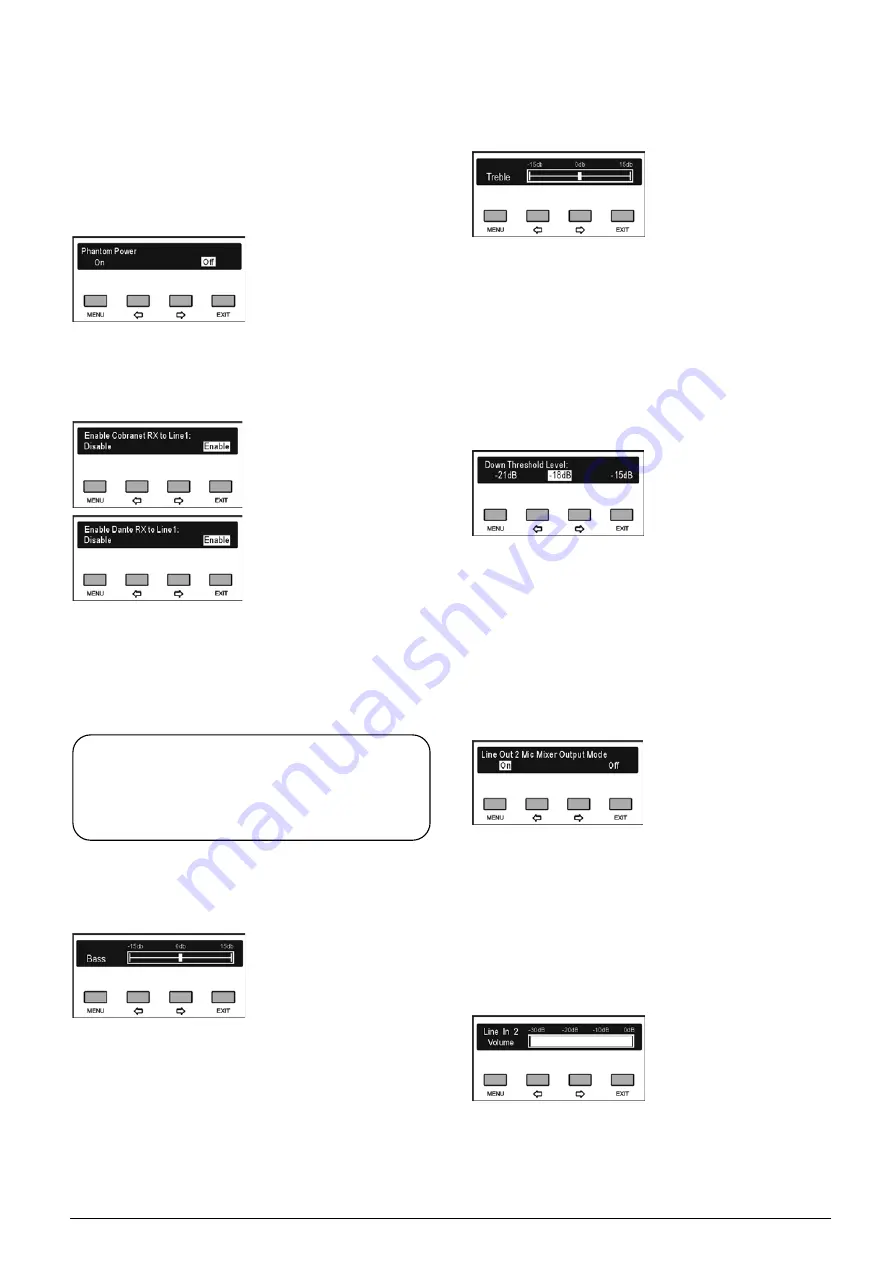
5. Down Treble Setting
Adjust downlink treble of contribution units (except
Interpreter units), range: -15 dB - 15 dB.
a). Press the “
/
” button to adjust;
b). Press the “MENU” button to save and return to
upper level menu.
6. Down Threshold Setting
Setup downlink audio threshold level to make sure that
the sound issuing from the built-in loudspeaker and the
headphone of each congress unit has no distortion.
a). Press the “
/
” button to select threshold level
between -21 dB, -18 dB and -15 dB;
b). Press the “MENU” button to save and return to
upper level menu.
7. Line Out 2 Mode Setting
Set up line out 2 microphone output mode, mixer or
not.
a). Press the “
/
” button to select “On” or “Off”;
b). Press the “MENU” button to save and return to the
upper level menu.
8. LINE IN 2 Volume Setting
Adjust LINE IN 2 input volume, range: mute, -30 dB -
0 dB.
a). Press the “
/
” button to adjust volume;
b). Press the “MENU” button to save and return to
upper level menu.
Note:
“down” and “downlink” used in 4./5. and 6. indicate
the signal transmission direction from the congress
main unit to the contribution units.
Summary of Contents for hcs-8300
Page 22: ...9 Figure 1 1 6 CongressMatrix TM Software Interface ...
Page 25: ...12 Figure 1 1 10 By using microphone array terminals the conference room looks tidy ...
Page 89: ...76 3 4 2 Installation Figure 3 4 2 Fixing of HCS 8336 SDI monitor ...
Page 93: ...80 B About Display the product information including unit ID serial and version ...
Page 168: ...155 Figure 6 1 3 CMU connecting to infrared language distribution system via HCS 8300MO ...
Page 210: ...197 6 9 2 Connection Figure 6 9 4 Connection between the HCS 8301M and the HCS 8300MAU FS ...
Page 249: ...236 Appendices Custom made cables AppendixⅠ Dedicated 6 PIN Extension Cable ...
Page 250: ...237 Appendix Ⅱ CBL2SS 01 Professional 2 pin Cable for Conference System ...
Page 251: ...238 Appendix Ⅲ CBL4PK 01 Power Adapter Cable ...
Page 252: ...239 Appendix Ⅳ CBL4PT 02 Power Branch Cable ...
Page 253: ...240 Appendix Ⅴ CBL4PS 4 pin Extension Cable ...
Page 254: ...241 Appendix Ⅵ Cat 6 Gigabit Ethernet Cable ...


