2-8
Setting the Operating and System Conditions
2
[6]
θθθθθ
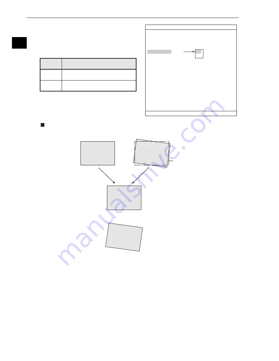
angle correction image display
Select "YES" or "NO" to display a
θ
angle corrected
image on the operation screen.
Display examples
(Reference image)
(Measured image)
Position of
reference image
- When the
q
angle correction
image display mode has
been set to YES.
- When the
q
angle correction
image display mode has
been set to NO.
1
MONITOR OUTPUT
CAM1
2
CAPTURE IMG
PARTIAL-IMG
3
MESSAGE DISPLAY
YES(NUMERIC)
4
PATTERN DISPLAY
YES
5
SHOW BINARY IMG
YES
6
SHOW
θ
FIX IMG
YES
7
OPS MAIN DISP
YES
8
DISP CHG-EVAL
NO
9
PC-MNTR
NO
0
THROUGH DISPLAY
NO
q
EXTENSION FUNC.
NO
TYPE RUN COND SCREEN SAVE
COLOR F C1 BRT
SET=SELECT A MENU ESC=BACK SEL=CHNG IMG TRG=FUNC
YES
NO
YES
NO
A
q
angle corrected image will be
displayed on the operation screen.
A
q
angle corrected image will not be
displayed on the operation screen.
Description
SHOW
FIX
q
IMG


