3.14 Selecting a location
Warning: Potential ignition source
This product is NOT approved for use in
hazardous/flammable atmospheres. Do
NOT install in a hazardous/flammable
atmosphere (such as in an engine room
or near fuel tanks).
General location requirements
When selecting a location for your product it is
important to consider a number of factors.
Key factors which can affect product performance
are:
•
Ventilation
To ensure adequate airflow:
– Ensure that product is mounted in a
compartment of suitable size.
– Ensure that ventilation holes are not obstructed.
Allow adequate separation of all equipment.
Any specific requirements for each system
component are provided later in this chapter.
•
Mounting surface
Ensure product is adequately supported on a
secure surface. Do not mount units or cut holes
in places which may damage the structure of the
vessel.
•
Cabling
Ensure the product is mounted in a location which
allows proper routing, support and connection of
cables:
– Minimum bend radius of 100 mm (3.94 in)
unless otherwise stated.
– Use cable clips to prevent stress on connectors.
– If your installation requires multiple ferrites to
be added to a cable then additional cable clips
should be used to ensure the extra weight of
the cable is supported.
•
Water ingress
The product is suitable for mounting both above
and below decks. Although the unit is waterproof,
it is good practice to locate it in a protected area
away from prolonged and direct exposure to rain
and salt spray.
•
Electrical interference
Select a location that is far enough away from
devices that may cause interference, such as
motors, generators and radio transmitters /
receivers.
•
Power supply
Select a location that is as close as possible to the
vessel’s DC power source. This will help to keep
cable runs to a minimum.
Compass safe distance
To prevent potential interference with the vessel's
magnetic compasses, ensure an adequate distance
is maintained from the display.
When choosing a suitable location for the
multifunction display you should aim to maintain the
maximum possible distance between the display and
any compasses. Typically this distance should be at
least 1 m (3 ft) in all directions. However for some
smaller vessels it may not be possible to locate
the display this far away from a compass. In this
situation, the following figures provide the minimum
safe distance that should be maintained between the
display and any compasses.
D
12203-1
2
00 m
m
(7.8
7 in)
350
mm
(13.8
in)
300
mm
(11.8
in)
70
0 m
m
(27
.5
in)
50
0 m
m
(19
.7
in)
250
mm
(9.8
4 in)
1
2
3
4
5
6
Item
Compass
position in
relation to
display
Minimum safe
distance from
display
1
Top
200 mm (7.87 in.)
2
Rear
500 mm (19.7 in.)
3
Right-hand side
350 mm (13.8 in.)
4
Underside
300 mm (11.8 in.)
5
Front
700 mm (27.5 in.)
6
Left-hand side
250 mm (9.84 in.)
GPS location requirements
In addition to general guidelines concerning the
location of marine electronics, there are a number
of environmental factors to consider when installing
equipment with an internal GPS antenna.
Mounting location
•
Above Decks mounting:
Provides optimal GPS performance. (For
equipment with appropriate waterproof rating.)
•
Below Decks mounting:
GPS performance may be less effective and may
require an external GPS antenna mounted above
decks.
46
a Series / c Series / e Series
Summary of Contents for c125
Page 2: ......
Page 14: ...14 a Series c Series e Series ...
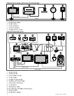
Page 41: ...13 GPS receiver 14 Thermal camera 15 Wireless connection Planning the installation 41 ...
Page 48: ...48 a Series c Series e Series ...
Page 80: ...80 a Series c Series e Series ...
Page 118: ...118 a Series c Series e Series ...
Page 184: ...184 a Series c Series e Series ...
Page 188: ...188 a Series c Series e Series ...
Page 206: ...206 a Series c Series e Series ...
Page 228: ...228 a Series c Series e Series ...
Page 290: ...290 a Series c Series e Series ...
Page 310: ...310 a Series c Series e Series ...
Page 340: ...340 a Series c Series e Series ...
Page 374: ...374 a Series c Series e Series ...
Page 422: ...422 a Series c Series e Series ...
Page 436: ...436 a Series c Series e Series ...
Page 462: ...462 a Series c Series e Series ...
Page 463: ......
Page 464: ...www raymarine com ...

