21.2 Multiple radar scanners
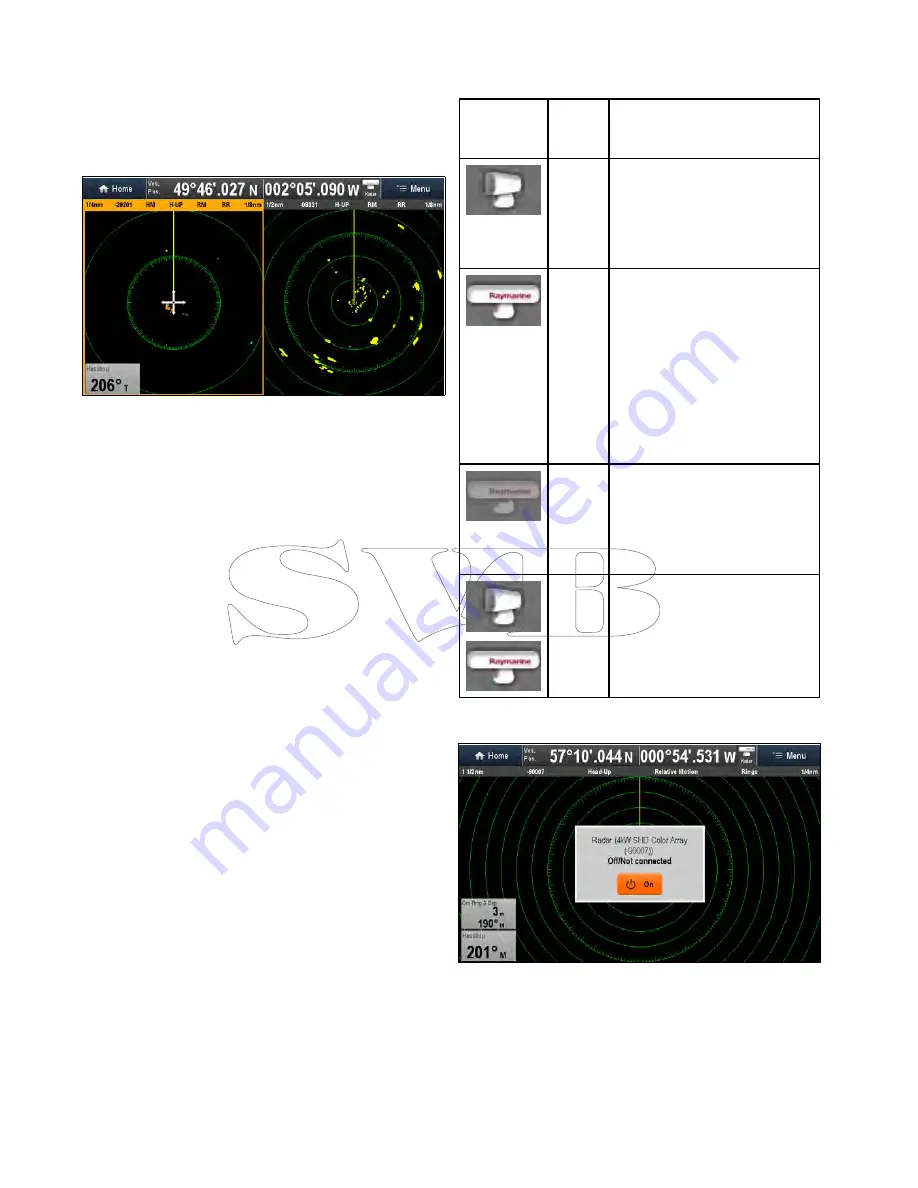
The multifunction display supports the use of up to 2
radar scanners on the same network.
For each radar application you can select which
radar scanner is displayed. 2 radar scanners can
be displayed simultaneously by creating a dual
splitscreen radar page on the Homescreen.
Selecting a radar scanner
On systems with 2 radar scanners, you can select
which radar scanner is displayed in each radar
application.
From the Radar application:
1. Select
Menu
.
2. Select
Select Radar
option.
3. Select the radar scanner that you want to display
in the current radar application.
The radar selection will be remembered by the
application and will be displayed automatically
the next time that application page is displayed.
21.3 Radar scanner status symbols
The radar scanner power mode status is indicated
in the databar.
Symbol
Radar
power
mode
Description
Trans-
mit (TX)
Rotating icon, signifying that the
scanner is on and transmitting.
When SCANNER is set to ON,
select this mode to activate the
scanner. This is the usual mode of
operation.
Standby
(STBY)
Static icon, indicating that the
scanner is on but not transmitting,
and the antenna is not rotating.
The scanner does not transmit and
the radar data is removed from the
screen. This is a power-save mode
used when the radar is not needed
for short time periods. When
you return to transmit mode, the
magnetron does not need to warm
up again. This is the default mode.
Off
Scanner powered off when radar
not required, but display is in use
for other applications, such as the
chart. When selected, the system
counts down. During this time you
cannot re-power the scanner.
Timed
Trans-
mit
Scanner switches between
on/transmitting, and standby mode.
Scanner goes into power save
mode when constant use of radar
is not required.
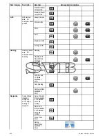
Powering on the radar scanner
From the Radar application, with the Radar scanner
powered off:
1. Select
On
from the onscreen .
The Radar scanner will power up in Standby
mode.
314
a Series / c Series / e Series
Summary of Contents for c125
Page 2: ......
Page 14: ...14 a Series c Series e Series ...
Page 41: ...13 GPS receiver 14 Thermal camera 15 Wireless connection Planning the installation 41 ...
Page 48: ...48 a Series c Series e Series ...
Page 80: ...80 a Series c Series e Series ...
Page 118: ...118 a Series c Series e Series ...
Page 184: ...184 a Series c Series e Series ...
Page 188: ...188 a Series c Series e Series ...
Page 206: ...206 a Series c Series e Series ...
Page 228: ...228 a Series c Series e Series ...
Page 290: ...290 a Series c Series e Series ...
Page 310: ...310 a Series c Series e Series ...
Page 340: ...340 a Series c Series e Series ...
Page 374: ...374 a Series c Series e Series ...
Page 422: ...422 a Series c Series e Series ...
Page 436: ...436 a Series c Series e Series ...
Page 462: ...462 a Series c Series e Series ...
Page 463: ......
Page 464: ...www raymarine com ...


