59
Data Exchange Method
Section 3-1
When setting data, select the
Set
Option.
3.
Use Monitor Plus to specify the Internal Switch’s tags for Monitor Plus and
write the data to the Internal Switch’s bits through the CPU Unit’s data ar-
ea.
4.
Use the Contact Distributor (Block Model 201) to write each internal
switch’s bit data to the specified function block’s bits.
5.
In the end, the bits will be set to the function block’s contact input ITEMs.
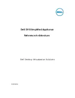
Monitoring Bits from
Monitor Plus
1,2,3...
1.
Connect the Contact Distributor (Block Model 201) as the source for the
function block’s contact input ITEM that you want to monitor. At the same
time, output (connect) from the Contact Distributor (Block Model 201) to
the Internal Switch (Block Model 209).
2.
Set the tags for Monitor Plus in the Internal Switch (Block Model 209). Set
a tag name for each ITEM (S1 to S8).
Monitor Plus
Loop Control Unit or Board
Internal
Switch
(Block
Model 209)
Set tags for Monitor Plus.
(Select
Display
to read data.)
Function
block
Function
block
Specify the tags
for Monitor Plus
and write data.
CPU Unit
Contact
Distributor
(Block
Model 201)
I/O memory
Summary of Contents for CX-Process Monitor Plus 2
Page 1: ...CX Process Monitor Plus Ver 2 Cat No W428 E1 02 SYSMAC WS02 LCMC1 EV2 OPERATION MANUAL...
Page 2: ...WS02 LCMC1 EV2 CX Process Monitor Plus Ver 2 Operation Manual Revised January 2007...
Page 3: ...iv...
Page 5: ...vi...
Page 9: ...x...
Page 15: ...xvi Application Precautions 4...
Page 41: ...26 Basic Operating Procedure Section 1 2...
Page 243: ...228 Checking Configurations Section 5 7...
Page 267: ...252 Reading Writing Function Block ITEMs Appendix A...
Page 269: ...254 Differences between Trend Screens and Batch Trend Screens Appendix B...