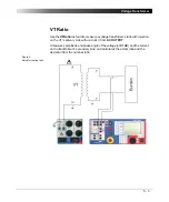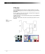
Voltage Transformer
5 - 15
Measurements
Once all settings are defined, press the I/O (test start/stop) push-button to start
the test.
The test voltage increases in a ramp characteristic from 0V to Vtest. Then Vtest
is kept and injected for the time period set in the "Time" data entry field and the
measurements are taken. Next, the ramp decreases again.
When the measurements are taken, finish the test by assessing it.
To learn more about test assessment, refer to ”Test Assessment” on page 10-2.
VAC:
injected voltage from
2kV AC
output at the time the test turned
off
IAC:
measured current between the transformer’s primary and
secondary windings at the time the test turned off
Imax:
maximum measured current between primary and secondary
winding during the entire test cycle
Summary of Contents for CPC 100
Page 12: ...CPC 100 V1 41 x...
Page 28: ...CPC 100 V1 41 1 16...
Page 90: ...CPC 100 V1 41 3 14...
Page 194: ...CPC 100 V1 41 6 30...
Page 250: ...CPC 100 V1 41 8 32 Figure 24 Settings of Amplifier test card for this example use case...
Page 258: ...CPC 100 V1 41 9 4...
Page 264: ...CPC 100 V1 41 10 6...
Page 282: ...CPC 100 V1 41 12 10 Figure 9 Saving tests with the CPC Editor...
Page 284: ...CPC 100 V1 41 12 12...
Page 312: ...CPC 100 V1 41 14 12...
Page 316: ...CPC 100 V1 41 15 4...
Page 350: ...CPC 100 V1 41 16 34...
Page 372: ...OMICRON Contact Addresses 22...


