


Transformer
6 - 17
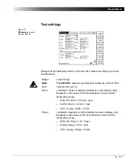
The "Temperature Compensation for Cu" Option
Option selected
Provides two more parameters to enter:
Depending on these two parameters, the reference resistance (Rref,
temperature-compensated winding resistance) is calculated:
Option cleared
For the winding resistance measurement there is no temperature compensation
taken into consideration.
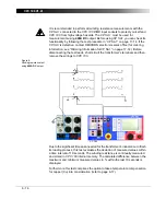
Once all settings are defined, press the I/O (test start/stop) push-button to start
the test.
When the measurements are taken, finish the test by assessing it.
To learn more about test assessment, refer to ”Test Assessment” on page 10-2.
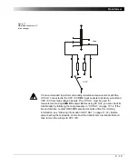
Tmeas:
ambient temperature
Tref:
operating temperature of test object, that is, the power
transformer’s secondary winding
Rref:
In Centigrade:
Rref = (VDC / IDC) x (235°C + Tref) / (235°C + Tmeas)
In Fahrenheit:
Rref = (VDC / IDC) x (391°F + Tref
F
) / (391°F + Tmeas
F
)
Note:
Formula according to IEC 60076-1.
Summary of Contents for CPC 100
Page 12: ...CPC 100 V1 41 x...
Page 28: ...CPC 100 V1 41 1 16...
Page 90: ...CPC 100 V1 41 3 14...
Page 194: ...CPC 100 V1 41 6 30...
Page 250: ...CPC 100 V1 41 8 32 Figure 24 Settings of Amplifier test card for this example use case...
Page 258: ...CPC 100 V1 41 9 4...
Page 264: ...CPC 100 V1 41 10 6...
Page 282: ...CPC 100 V1 41 12 10 Figure 9 Saving tests with the CPC Editor...
Page 284: ...CPC 100 V1 41 12 12...
Page 312: ...CPC 100 V1 41 14 12...
Page 316: ...CPC 100 V1 41 15 4...
Page 350: ...CPC 100 V1 41 16 34...
Page 372: ...OMICRON Contact Addresses 22...


