


Others - Ramping
8 - 23
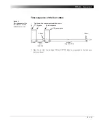
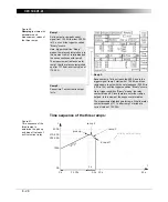
Example of a series of ramps
Figure 17:
A series of three ramps
defined in the ramps
table
The three ramps defined in the ramps table shown above result in an output
signal like this:
Ramp 1
•
from 1A
(set at "Start val:")
•
to end value 200A
(set in line 1 at column "A")
•
in 5 s
(set in line 1 at column "s")
Ramp 2
•
from 200A
(end value of ramp 1)
•
to end value 200A
(set in line 2 at column "A")
•
for 10 seconds
(set in line 2 at column "s")
Ramp 3
•
from 200A
(end value of ramp 2)
•
to end value 0A
(set in line 3 at column "A")
•
in 5 seconds
(set in line 3 at column "s")
Ramp 1
Ramp 2
Ramp 3
t
5s
15s
I
20s
1A
200A
R
am
p 1
Ramp 2
R
amp
3
0s
Summary of Contents for CPC 100
Page 12: ...CPC 100 V1 41 x...
Page 28: ...CPC 100 V1 41 1 16...
Page 90: ...CPC 100 V1 41 3 14...
Page 194: ...CPC 100 V1 41 6 30...
Page 250: ...CPC 100 V1 41 8 32 Figure 24 Settings of Amplifier test card for this example use case...
Page 258: ...CPC 100 V1 41 9 4...
Page 264: ...CPC 100 V1 41 10 6...
Page 282: ...CPC 100 V1 41 12 10 Figure 9 Saving tests with the CPC Editor...
Page 284: ...CPC 100 V1 41 12 12...
Page 312: ...CPC 100 V1 41 14 12...
Page 316: ...CPC 100 V1 41 15 4...
Page 350: ...CPC 100 V1 41 16 34...
Page 372: ...OMICRON Contact Addresses 22...


