


CPC 100 V1.41
4 - 22
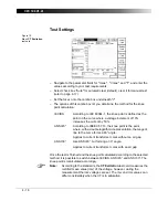
Test settings
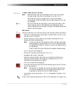
Figure 14:
RWinding
test card
with test results
Navigate to the parameter fields, and enter the values according to your test
requirements:
Note:
The transformer’s core is magnetized after the measurement.
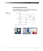
Demagnetization can be done using the
CT Excitation
test card (see ”CT
Excitation (Kneepoint)” on page 15 of this chapter.
Range:
output range (Use the
6A DC
output for measuring CTs.)
Itest:
nominal test current
R min:
calculated minimum winding resistance value (display only).
Depends on the value of the nominal test current and the
measuring range:
– 400A DC: Rmin = 0.2mV / Itest
– 6A DC: Rmin = 0.2mV / Itest
– V DC (2-wire): Rmin = 0.2
Ω
R max:
calculated maximum winding resistance value (display only).
Depends on the value of the nominal test current and the
measuring range:
– 400A DC: Rmax = 5V / Itest.
– 6A DC: Rmax = 10V / Itest.
– V DC (2-wire): Rmax = 20k
Ω
Summary of Contents for CPC 100
Page 12: ...CPC 100 V1 41 x...
Page 28: ...CPC 100 V1 41 1 16...
Page 90: ...CPC 100 V1 41 3 14...
Page 194: ...CPC 100 V1 41 6 30...
Page 250: ...CPC 100 V1 41 8 32 Figure 24 Settings of Amplifier test card for this example use case...
Page 258: ...CPC 100 V1 41 9 4...
Page 264: ...CPC 100 V1 41 10 6...
Page 282: ...CPC 100 V1 41 12 10 Figure 9 Saving tests with the CPC Editor...
Page 284: ...CPC 100 V1 41 12 12...
Page 312: ...CPC 100 V1 41 14 12...
Page 316: ...CPC 100 V1 41 15 4...
Page 350: ...CPC 100 V1 41 16 34...
Page 372: ...OMICRON Contact Addresses 22...


