


CPC 100 V1.41
8 - 14
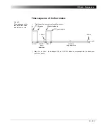
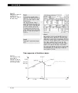
Measuring a CT Ratio at Different Current
Magnitudes
Example of a sequence of five states to measure the ratio of a current
transformer. To do so, different current amplitudes (5%, 20%, 50%, 100% and
120% of nominal value) are injected into the CT, and the CT’s secondary current
is measured at
CPC 100
current input
IAC/DC
.
Figure 9:
Setup to measure the
ratio of a current
transformer at different
current magnitudes
Parameters of the states 1 ... 5
Each of the five states injects a current with a different magnitude into the CT’s
primary winding. There is no trigger specified, so each state runs exactly 2s.
A
Hz
Trigger
Thresh
s
20 (= 5%)
50.00
No Trigger
n/a
2.000
80 (= 20%)
50.00
No Trigger
n/a
2.000
200 (= 50%)
50.00
No Trigger
n/a
2.000
400 (= 100%)
50.00
No Trigger
n/a
2.000
480 (= 120%)
50.00
No Trigger
n/a
2.000
Summary of Contents for CPC 100
Page 12: ...CPC 100 V1 41 x...
Page 28: ...CPC 100 V1 41 1 16...
Page 90: ...CPC 100 V1 41 3 14...
Page 194: ...CPC 100 V1 41 6 30...
Page 250: ...CPC 100 V1 41 8 32 Figure 24 Settings of Amplifier test card for this example use case...
Page 258: ...CPC 100 V1 41 9 4...
Page 264: ...CPC 100 V1 41 10 6...
Page 282: ...CPC 100 V1 41 12 10 Figure 9 Saving tests with the CPC Editor...
Page 284: ...CPC 100 V1 41 12 12...
Page 312: ...CPC 100 V1 41 14 12...
Page 316: ...CPC 100 V1 41 15 4...
Page 350: ...CPC 100 V1 41 16 34...
Page 372: ...OMICRON Contact Addresses 22...


