CPC 100 V1.41
8 - 20
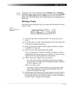
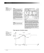
Next, set the ramp(s) parameters, that is, the parameters that apply to this
particular ramp only. Each line of the ramps table represents one ramp.
Figure 16:
Step 2 - Set the ramp
parameters
Turn the handwheel to set the focus onto the ramps table’s first cell; in
Figure 16 above it is the output current. Then press the handwheel. The
cell turns into an entry field. Now set the output current value of your
choice by turning the handwheel, or use the number keys of
CPC 100
soft-touch keyboard. Press E
N T E R
or the handwheel to acknowledge
your setting and move to the next table cell by turning the handwheel.
Note that the units of the ramps table (the table’s columns) depend on
the selected output range.
Duration of ramp, that is, the time this particular ramp sweeps the
selected signal from the start to the end value.
After this period of time the ramp terminates and the series continues
with the next ramp (if any).
If a trigger signal occurs
before
this time has elapsed, the currently
running ramp terminates and the series continues with the next ramp. If
"SOOT" is selected, the trigger signal terminates the complete series of
ramps.
7
8
10
9
7
8
Summary of Contents for CPC 100
Page 12: ...CPC 100 V1 41 x...
Page 28: ...CPC 100 V1 41 1 16...
Page 90: ...CPC 100 V1 41 3 14...
Page 194: ...CPC 100 V1 41 6 30...
Page 250: ...CPC 100 V1 41 8 32 Figure 24 Settings of Amplifier test card for this example use case...
Page 258: ...CPC 100 V1 41 9 4...
Page 264: ...CPC 100 V1 41 10 6...
Page 282: ...CPC 100 V1 41 12 10 Figure 9 Saving tests with the CPC Editor...
Page 284: ...CPC 100 V1 41 12 12...
Page 312: ...CPC 100 V1 41 14 12...
Page 316: ...CPC 100 V1 41 15 4...
Page 350: ...CPC 100 V1 41 16 34...
Page 372: ...OMICRON Contact Addresses 22...


