5. PARAMETERS
5 - 41
No.
Symbol
Name and function
Initial
value
[unit]
Setting
range
Each/
Common
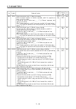
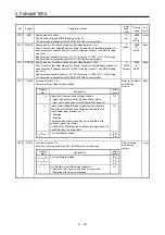
PC20
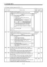
*COP7 Function selection C-7
Select the detection method of [AL. 10 Undervoltage].
Refer to Name
and function
column.
Common
Setting
digit
Explanation
Initial
value
_ _ _ x
For manufacturer setting
0h
_ _ x _
0h
_ x _ _
Undervoltage alarm selection
Select the alarm/alarm and warning for when the bus
voltage drops to the undervoltage alarm level.
0: [AL. 10] regardless of servo motor speed
1: [AL. E9] at servo motor speed 50 r/min (50 mm/s) or
less, [AL. 10] at over 50 r/min (50 mm/s)
0h
x _ _ _
For manufacturer setting
0h
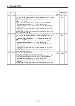
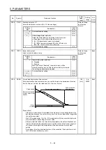
PC21
*BPS
Alarm history clear
Used to clear the alarm history.
Refer to Name
and function
column.
Each
Setting
digit
Explanation
Initial
value
_ _ _ x
Alarm history clear selection
0: Disabled
1: Enabled
When you select "Enabled", the alarm history will be
cleared at next power-on. After the alarm history is cleared,
the setting is automatically disabled.
0h
_ _ x _
For manufacturer setting
0h
_ x _ _
0h
x _ _ _
0h
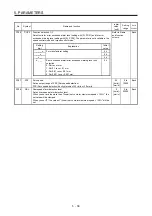
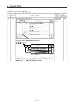
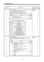
PC24
RSBR
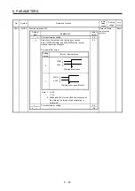
Forced stop deceleration time constant
Set a deceleration time constant when you use the forced stop deceleration function.
Set the time per ms from the rated speed to 0 r/min or 0 mm/s.
Forced stop deceleration
[Pr.PC24]
0 r/min
(0 mm/s)
Servo motor speed
(Linear servo motor
speed)
Rated speed
Dynamic brake
deceleration
[Precautions]
If the servo motor torque is saturated at the maximum torque during forced stop
deceleration because the set time is too short, the time to stop will be longer than
the set time constant.
[AL. 50 Overload alarm 1] or [AL. 51 Overload alarm 2] may occur during forced
stop deceleration, depending on the set value.
After an alarm that leads to a forced stop deceleration, if an alarm that does not
lead to a forced stop deceleration occurs or if the control circuit power supply is
cut, dynamic braking will start regardless of the deceleration time constant
setting.
Set a longer time than deceleration time of the controller. If a shorter time is set,
[AL. 52 Error excessive] may occur.
100
[ms]
0 to
20000
Each
Summary of Contents for MR-J4W2
Page 9: ...A 8 MEMO ...
Page 17: ...8 MEMO ...
Page 31: ...1 FUNCTIONS AND CONFIGURATION 1 14 MEMO ...
Page 95: ...4 STARTUP 4 20 MEMO ...
Page 169: ...6 NORMAL GAIN ADJUSTMENT 6 20 MEMO ...
Page 201: ...7 SPECIAL ADJUSTMENT FUNCTIONS 7 32 MEMO ...
Page 213: ...8 TROUBLESHOOTING 8 12 MEMO ...
Page 219: ...9 OUTLINE DRAWINGS 9 6 MEMO ...
Page 229: ...10 CHARACTERISTICS 10 10 MEMO ...
Page 295: ...13 USING STO FUNCTION 13 14 MEMO ...
Page 327: ...14 USING A LINEAR SERVO MOTOR 14 32 MEMO ...
Page 371: ...16 FULLY CLOSED LOOP SYSTEM 16 24 MEMO ...
Page 521: ...APPENDIX App 38 ...
Page 537: ...MEMO ...
Page 541: ......


