5. PARAMETERS
5 - 44
No.
Symbol
Name and function
Initial
value
[unit]
Setting
range
Each/
Common
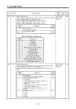
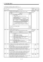
PD07
*DO1
Output device selection 1
You can assign any output device to pins CN3-12, CN3-13, and CN3-25. In the initial
setting, the following devices are assigned to the pins.
CN3-12 pin: MBR-A (Electromagnetic brake interlock for A-axis)
CN3-13 pin: MBR-C (Electromagnetic brake interlock for C-axis)
CN3-25 pin: MBR-B (Electromagnetic brake interlock for B-axis)
Refer to Name
and function
column.
Each
Setting
digit
Explanation
Initial
value
_ _ x x
Device selection
Refer to table 5.8 for settings.
05h
_ x _ _
For manufacturer setting
0h
x _ _ _
0h
Table 5.8 Selectable output devices
Setting
value
Output device
00
Always
off
02
RD
(Ready)
03
ALM
(Malfunction)
04
INP
(In-position)
05
MBR (Electromagnetic brake interlock)
07
TLC (Limiting torque)
08
WNG
(Warning)
09
BWNG (Battery warning)
0A
SA (Speed reached)
0C
ZSP (Zero speed detection)
0F
CDPS (Variable gain selection)
10
CLDS (During fully closed loop control)
11
ABSV (Absolute position undetermined)
17
MTTR (During tough drive)
PD08
*DO2
Output device selection 2
You can assign any output device to the CN3-24 pin for each axis. CINP (AND in-
position) is assigned to the all axes in the initial setting.
The devices that can be assigned and the setting method are the same as in [Pr.
PD07].
Refer to Name
and function
column.
Common
Setting
digit
Explanation
Initial
value
_ _ x x
Device selection
Refer to table 5.8 in [Pr. PD07] for settings.
04h
_ x _ _
All-axis output condition selection
0: AND output
When all axes of A, B, and C meet a condition, the
device will be enabled (on or off).
1: OR output
When each axis of A, B, or C meet a condition, the
device will be enabled (on or off).
The digit will be enabled when "All axes (0 _ _ _)" is
selected.
0h
x _ _ _
Output axis selection
0: All axes
1: A-axis
2: B-axis
3: C-axis
0h
Summary of Contents for MR-J4W2
Page 9: ...A 8 MEMO ...
Page 17: ...8 MEMO ...
Page 31: ...1 FUNCTIONS AND CONFIGURATION 1 14 MEMO ...
Page 95: ...4 STARTUP 4 20 MEMO ...
Page 169: ...6 NORMAL GAIN ADJUSTMENT 6 20 MEMO ...
Page 201: ...7 SPECIAL ADJUSTMENT FUNCTIONS 7 32 MEMO ...
Page 213: ...8 TROUBLESHOOTING 8 12 MEMO ...
Page 219: ...9 OUTLINE DRAWINGS 9 6 MEMO ...
Page 229: ...10 CHARACTERISTICS 10 10 MEMO ...
Page 295: ...13 USING STO FUNCTION 13 14 MEMO ...
Page 327: ...14 USING A LINEAR SERVO MOTOR 14 32 MEMO ...
Page 371: ...16 FULLY CLOSED LOOP SYSTEM 16 24 MEMO ...
Page 521: ...APPENDIX App 38 ...
Page 537: ...MEMO ...
Page 541: ......


