18. MR-J4W2-0303B6 SERVO AMPLIFIER
18 - 26
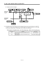
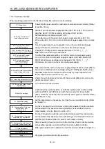
18.3.6 Connectors and pin assignment
POINT
The pin assignment of the connectors is as viewed from the cable connector
wiring section.
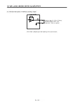
For the CN3 connector, securely connect the external conductor of the shielded
cable to the ground plate and fix it to the connector shell.
Screw
Screw
Ground plate
Cable
14
LG
LA-A
1
15
2
16
3
17
4
18
5
19
6
20
7
21
8
22
9
23
10
24
11
25
12
26
13
LBR-A
LAR-A
LB-A
LA-B
LBR-B
LAR-B
LB-B
DI1-A
DI2-B
DI1-B
DI2-A
DI3-A
DICOM
DI3-B
EM2
CALM
MBR-B
CINP
MBR-A
DOCOM
CN3
MO1
LG
MO2
5A
5B
CN2A
SHD
BAT
4A
4B
P5
LG
3A
3B
2A
2B
1A
1B
MR
MRR
CN2B
5A
5B
SHD
BAT
4A
4B
P5
LG
3A
3B
2A
2B
1A
1B
MR
MRR
Summary of Contents for MR-J4W2
Page 9: ...A 8 MEMO ...
Page 17: ...8 MEMO ...
Page 31: ...1 FUNCTIONS AND CONFIGURATION 1 14 MEMO ...
Page 95: ...4 STARTUP 4 20 MEMO ...
Page 169: ...6 NORMAL GAIN ADJUSTMENT 6 20 MEMO ...
Page 201: ...7 SPECIAL ADJUSTMENT FUNCTIONS 7 32 MEMO ...
Page 213: ...8 TROUBLESHOOTING 8 12 MEMO ...
Page 219: ...9 OUTLINE DRAWINGS 9 6 MEMO ...
Page 229: ...10 CHARACTERISTICS 10 10 MEMO ...
Page 295: ...13 USING STO FUNCTION 13 14 MEMO ...
Page 327: ...14 USING A LINEAR SERVO MOTOR 14 32 MEMO ...
Page 371: ...16 FULLY CLOSED LOOP SYSTEM 16 24 MEMO ...
Page 521: ...APPENDIX App 38 ...
Page 537: ...MEMO ...
Page 541: ......


