17. APPLICATION OF FUNCTIONS
17 - 5
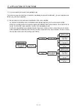
17.1.4 How to switch J4 mode/J3 compatibility mode
There are two ways to switch the J4 mode/J3 compatibility mode with the MR-J4W_-_B servo amplifier and
MR-J4-_B_(-RJ) servo amplifier.
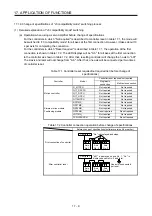
(1) Mode selection by the automatic identification of the servo amplifier
J4 mode/J3 compatibility mode is identified automatically depending on the connected controller.
When the controller make a connection request with SSCNET III/H communication, the mode will be "J4
mode". For SSCNET communication, it will be "J3 compatibility mode".
For the J3 compatibility mode, standard control, linear servo motor control, or direct drive motor control
will be identified automatically with a motor (encoder) connected to the servo amplifier. For the J4 mode,
the operation mode will be the setting of [Pr. PA01].
J4 mode/J3 compatibility
mode automatic
identification
Controller
connection check
J4 mode
J3 compatibility
mode
Connected encoder
check (automatic
identification)
Standard control
(rotary servo motor)
Direct drive motor
control
Factory setting
Linear servo motor
control
Fully closed
loop control
[Pr. PA01] setting
Standard control
(rotary servo motor)
Direct drive motor
control
Linear servo motor
control
Fully closed
loop control
Summary of Contents for MR-J4W2
Page 9: ...A 8 MEMO ...
Page 17: ...8 MEMO ...
Page 31: ...1 FUNCTIONS AND CONFIGURATION 1 14 MEMO ...
Page 95: ...4 STARTUP 4 20 MEMO ...
Page 169: ...6 NORMAL GAIN ADJUSTMENT 6 20 MEMO ...
Page 201: ...7 SPECIAL ADJUSTMENT FUNCTIONS 7 32 MEMO ...
Page 213: ...8 TROUBLESHOOTING 8 12 MEMO ...
Page 219: ...9 OUTLINE DRAWINGS 9 6 MEMO ...
Page 229: ...10 CHARACTERISTICS 10 10 MEMO ...
Page 295: ...13 USING STO FUNCTION 13 14 MEMO ...
Page 327: ...14 USING A LINEAR SERVO MOTOR 14 32 MEMO ...
Page 371: ...16 FULLY CLOSED LOOP SYSTEM 16 24 MEMO ...
Page 521: ...APPENDIX App 38 ...
Page 537: ...MEMO ...
Page 541: ......

