7. SPECIAL ADJUSTMENT FUNCTIONS
7 - 27
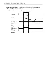
(2) Instantaneous power failure time of the control circuit power supply < [Pr. PF25 SEMI-F47 function -
Instantaneous power failure detection time]
Operation status differs depending on how bus voltage decrease.
(a) When the bus voltage decrease lower than 158 V DC within the instantaneous power failure time of
the control circuit power supply
[AL. 10 Undervoltage] occurs when the bus voltage decrease lower than 158 V DC regardless of the
enabled instantaneous power failure tough drive.
[Pr. PF25]
Instantaneous power failure time of the control circuit power supply
ON
OFF
ON
OFF
ON
OFF
ON
OFF
ON
OFF
ON
OFF
Control circuit
power supply
Bus voltage
Undervoltage level
(158 V DC)
CALM
(AND malfunction)
MTTR
(During tough drive)
MBR
(Electromagnetic
brake interlock)
Base circuit
WNG
(Warning)
Summary of Contents for MR-J4W2
Page 9: ...A 8 MEMO ...
Page 17: ...8 MEMO ...
Page 31: ...1 FUNCTIONS AND CONFIGURATION 1 14 MEMO ...
Page 95: ...4 STARTUP 4 20 MEMO ...
Page 169: ...6 NORMAL GAIN ADJUSTMENT 6 20 MEMO ...
Page 201: ...7 SPECIAL ADJUSTMENT FUNCTIONS 7 32 MEMO ...
Page 213: ...8 TROUBLESHOOTING 8 12 MEMO ...
Page 219: ...9 OUTLINE DRAWINGS 9 6 MEMO ...
Page 229: ...10 CHARACTERISTICS 10 10 MEMO ...
Page 295: ...13 USING STO FUNCTION 13 14 MEMO ...
Page 327: ...14 USING A LINEAR SERVO MOTOR 14 32 MEMO ...
Page 371: ...16 FULLY CLOSED LOOP SYSTEM 16 24 MEMO ...
Page 521: ...APPENDIX App 38 ...
Page 537: ...MEMO ...
Page 541: ......


