16. FULLY CLOSED LOOP SYSTEM
16 - 1
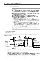
16. FULLY CLOSED LOOP SYSTEM
POINT
The fully closed loop system is available for the MR-J4-W2-_B servo amplifiers
of which software version is A3 or above. It will not be available with MR-J4W3-
_B.
When fully closed loop control system is used with this servo amplifier, "Linear
Encoder Instruction Manual" is needed.
Fully closed loop control system is available with position control mode.
When fully closed loop control system is configured with MR-J4W2-_B servo
amplifier, the following restrictions apply.
A/B/Z-phase differential output type encoder cannot be used.
The load-side encoder and servo motor encoder is compatible with only the
two-wire type. The four-wire type load-side encoder and servo motor encoder
cannot be used.
When you use the KG-KR and HG-MR series for driving and load-side
encoder, the optional four-wire type encoder cables (MR-EKCBL30M-L, MR-
EKCBL30M-H, MR-EKCBL40M-H, and MR-EKCBL50M-H) cannot be used.
When an encoder cable of 30 m to 50 m is needed, fabricate a two-wire type
encoder cable according to appendix 8.
The MR-J4W2-0303B6 servo amplifier is not compatible with the fully closed
loop system.
16.1 Functions and configuration
16.1.1 Function block diagram
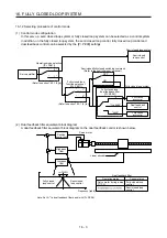
A fully closed loop control block diagram is shown below. The fully closed loop system is controlled in the
load-side encoder unit.
Servo motor-side cumulative
feedback pulses
(load-side encoder resolution unit)
(Servo motor side)
Droop pulses
(Servo motor side)
Cumulative
feedback pulses
Load-side
droop pulses
Cumulative load-side
feedback pulses
Dual
feedback filter
([Pr. PE08])
(Note 2)
FBD
Servo motor
Linear encoder
Controller
(Note 1, 2)
Fully closed loop selection
([Pr. PE01] and [Pr. PE08])
+
-
FBN
S
+
-
Encoder pulse setting
([Pr. PA15], [Pr. PA16]
and [Pr. PC03])
Fully closed loop control
error detection function
selection ([Pr. PE03])
+
-
+
+
-
+
-
+
Control
Monitor
Load-side feedback pulses
Note 1. Switching between semi closed loop control and fully closed loop control can be performed by changing the setting of [Pr.
PE01].
When semi closed loop control is selected, a control is always performed on the bases of the position data of the servo
motor encoder independently of whether the servo motor is at a stop or running.
2. When the fully closed loop system is enabled in [Pr. PE01], dual feedback control in which the servo motor feedback signal
and load-side encoder feedback signal are combined by the dual feedback filter in [Pr. PE08] is performed.
In this case, fully closed loop control is performed when the servo motor is at a stop, and semi closed loop control is
performed when the servo motor is operating to improve control performance. When "4500" is set as the filter value of [Pr.
PE08 Dual feedback filter], fully closed loop control is always performed.
Summary of Contents for MR-J4W2
Page 9: ...A 8 MEMO ...
Page 17: ...8 MEMO ...
Page 31: ...1 FUNCTIONS AND CONFIGURATION 1 14 MEMO ...
Page 95: ...4 STARTUP 4 20 MEMO ...
Page 169: ...6 NORMAL GAIN ADJUSTMENT 6 20 MEMO ...
Page 201: ...7 SPECIAL ADJUSTMENT FUNCTIONS 7 32 MEMO ...
Page 213: ...8 TROUBLESHOOTING 8 12 MEMO ...
Page 219: ...9 OUTLINE DRAWINGS 9 6 MEMO ...
Page 229: ...10 CHARACTERISTICS 10 10 MEMO ...
Page 295: ...13 USING STO FUNCTION 13 14 MEMO ...
Page 327: ...14 USING A LINEAR SERVO MOTOR 14 32 MEMO ...
Page 371: ...16 FULLY CLOSED LOOP SYSTEM 16 24 MEMO ...
Page 521: ...APPENDIX App 38 ...
Page 537: ...MEMO ...
Page 541: ......


