18. MR-J4W2-0303B6 SERVO AMPLIFIER
18 - 37
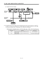
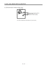
(1) Internal connection diagram
EM2
CN3
DICOM
23
CN3
Servo amplifier
(Note 1)
USB
D+
GND
D-
2
3
5
CN5
(Note 4)
24 V DC
(Note 2)
DI1-A
DI2-A
DI3-A
DI1-B
DI2-B
DI3-B
10
7
8
9
20
21
22
25
11
24
MBR-B
12
MBR-A
26
DOCOM
CALM
(Note 3)
(Note 2)
RA
RA
CN3
3
16
4
17
5
18
LA-A
1A
4B
1B
MR
MRR
LG
Encoder
E1
M
CN2A
6
19
LAR-A
LB-A
LBR-A
LA-B
LAR-B
LB-B
LBR-B
14
LG
CNP1
9
Insulated
A-axis servo motor
1A
4B
1B
MR
MRR
LG
Encoder
E2
M
CN2B
CNP1
7
B-axis servo motor
Approx.
5.6 k
Ω
Approx.
5.6 k
Ω
Differential line
driver output
(35 mA or lower)
(Note 4)
24 V DC
10 V DC
± 5 V
CN3
MO1
MO2
2
15
Analog monitor
10 V DC
± 5 V
LG
1
CNP1
11
Note 1. Signal can be assigned for these pins with the controller setting.
For contents of signals, refer to the instruction manual of the controller.
2. This is for the sink I/O interface. For source I/O interface, refer to section 3.8.3.
3. In the initial setting, CINP (AND in-position) is assigned to the pin. You can change devices of the pin with [Pr. PD08].
4. The illustration of the 24 V DC power supply is divided between input signal and output signal for convenience. However, they
can be configured by one.
The 24 V DC power for I/O signal, use power other than 24 V DC power of servo amplifier control circuit power supply.
Summary of Contents for MR-J4W2
Page 9: ...A 8 MEMO ...
Page 17: ...8 MEMO ...
Page 31: ...1 FUNCTIONS AND CONFIGURATION 1 14 MEMO ...
Page 95: ...4 STARTUP 4 20 MEMO ...
Page 169: ...6 NORMAL GAIN ADJUSTMENT 6 20 MEMO ...
Page 201: ...7 SPECIAL ADJUSTMENT FUNCTIONS 7 32 MEMO ...
Page 213: ...8 TROUBLESHOOTING 8 12 MEMO ...
Page 219: ...9 OUTLINE DRAWINGS 9 6 MEMO ...
Page 229: ...10 CHARACTERISTICS 10 10 MEMO ...
Page 295: ...13 USING STO FUNCTION 13 14 MEMO ...
Page 327: ...14 USING A LINEAR SERVO MOTOR 14 32 MEMO ...
Page 371: ...16 FULLY CLOSED LOOP SYSTEM 16 24 MEMO ...
Page 521: ...APPENDIX App 38 ...
Page 537: ...MEMO ...
Page 541: ......


