5. PARAMETERS
5 - 38
No.
Symbol
Name and function
Initial
value
[unit]
Setting
range
Each/
Common
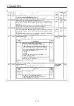
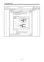
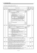
PC06
*COP3 Function selection C-3
Select units for error excessive alarm level setting with [Pr. PC01] and for error
excessive warning level setting with [Pr. PC38]. The parameter is not available in the
speed control mode and torque control mode.
Refer to Name
and function
column.
Each
Setting
digit
Explanation
Initial
value
_ _ _ x
For manufacturer setting
0h
_ _ x _
0h
_ x _ _
0h
x _ _ _
Error excessive alarm/error excessive warning level unit
selection
0: Per rev or mm
1: Per 0.1 rev or 0.1 mm
2: Per 0.01 rev or 0.01 mm
3: Per 0.001 rev or 0.001 mm
0h
PC07 ZSP Zero
speed
Set an output range of ZSP (Zero speed detection).
ZSP (Zero speed detection) has hysteresis of 20 r/min or 20 mm/s.
50
[r/min]/
[mm/s]
0 to
10000
Each
PC08
OSL
Overspeed alarm detection level
Set an overspeed alarm detection level.
When you set a value more than "(linear) servo motor maximum speed × 120%", the
set value will be clamped.
When you set "0", the value of "(linear) servo motor maximum speed × 120%" will be
set.
0
[r/min]/
[mm/s]
0 to
20000
Each
Summary of Contents for MR-J4W2
Page 9: ...A 8 MEMO ...
Page 17: ...8 MEMO ...
Page 31: ...1 FUNCTIONS AND CONFIGURATION 1 14 MEMO ...
Page 95: ...4 STARTUP 4 20 MEMO ...
Page 169: ...6 NORMAL GAIN ADJUSTMENT 6 20 MEMO ...
Page 201: ...7 SPECIAL ADJUSTMENT FUNCTIONS 7 32 MEMO ...
Page 213: ...8 TROUBLESHOOTING 8 12 MEMO ...
Page 219: ...9 OUTLINE DRAWINGS 9 6 MEMO ...
Page 229: ...10 CHARACTERISTICS 10 10 MEMO ...
Page 295: ...13 USING STO FUNCTION 13 14 MEMO ...
Page 327: ...14 USING A LINEAR SERVO MOTOR 14 32 MEMO ...
Page 371: ...16 FULLY CLOSED LOOP SYSTEM 16 24 MEMO ...
Page 521: ...APPENDIX App 38 ...
Page 537: ...MEMO ...
Page 541: ......


