8. TROUBLESHOOTING
8 - 9
No.
Name
Detail
No.
Detail name
Stop
method
(Note 2,
3)
Process-
ing
system
Stop
system
Warning
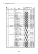
F0
Tough drive warning
F0.1
Instantaneous power failure tough
drive warning
Each
axis
F0.3 Vibration tough drive warning
Each axis
F2
Drive recorder -
Miswriting warning
F2.1
Drive recorder - Area writing time-
out warning
Common
F2.2
Drive recorder - Data miswriting
warning
Common
F3
Oscillation detection
warning
F3.1 Oscillation detection warning
Each axis
Note 1. Leave for about 30 minutes of cooling time after removing the cause of occurrence.
2. The following shows two stop methods of DB and SD.
DB: Dynamic brake stop (For a servo amplifier without the dynamic brake, the servo motor coasts.)
Coasts for MR-J4W2-0303B6.
SD: Forced stop deceleration
3. This is applicable when [Pr. PA04] is set to the initial value. The stop system of SD can be changed to DB using
[Pr. PA04].
4. Quick stop or slow stop can be selected using [Pr. PD30].
Summary of Contents for MR-J4W2
Page 9: ...A 8 MEMO ...
Page 17: ...8 MEMO ...
Page 31: ...1 FUNCTIONS AND CONFIGURATION 1 14 MEMO ...
Page 95: ...4 STARTUP 4 20 MEMO ...
Page 169: ...6 NORMAL GAIN ADJUSTMENT 6 20 MEMO ...
Page 201: ...7 SPECIAL ADJUSTMENT FUNCTIONS 7 32 MEMO ...
Page 213: ...8 TROUBLESHOOTING 8 12 MEMO ...
Page 219: ...9 OUTLINE DRAWINGS 9 6 MEMO ...
Page 229: ...10 CHARACTERISTICS 10 10 MEMO ...
Page 295: ...13 USING STO FUNCTION 13 14 MEMO ...
Page 327: ...14 USING A LINEAR SERVO MOTOR 14 32 MEMO ...
Page 371: ...16 FULLY CLOSED LOOP SYSTEM 16 24 MEMO ...
Page 521: ...APPENDIX App 38 ...
Page 537: ...MEMO ...
Page 541: ......


