3. SIGNALS AND WIRING
3 - 12
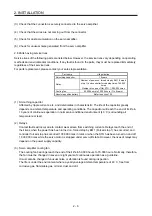
You can also use a ferrule to connect with the connectors. When you use a ferrule, use the following
ferrules and crimp terminal.
Wire size
Ferrule model (Phenix contact)
Crimping tool
(Phenix contact)
For 1 wire
For 2 wires
AWG16 AI1.5-10BK AI-TWIN2×1.5-10BK
CRIMPFOX-ZA3
AWG14 AI2.5-10BU
(b) Inserting wire
Insert the open tool as follows and push down it to open the spring. While the open tool is pushed
down, insert the stripped wire into the wire insertion hole. Check the insertion depth so that the cable
insulator does not get caught by the spring.
Release the open tool to fix the wire. Pull the wire lightly to confirm that the wire is surely connected.
The following shows a connection example of the CNP1 connector.
1) Push down the open tool.
3) Release the open tool to fix the wire.
2) Insert the wire.
Summary of Contents for MR-J4W2
Page 9: ...A 8 MEMO ...
Page 17: ...8 MEMO ...
Page 31: ...1 FUNCTIONS AND CONFIGURATION 1 14 MEMO ...
Page 95: ...4 STARTUP 4 20 MEMO ...
Page 169: ...6 NORMAL GAIN ADJUSTMENT 6 20 MEMO ...
Page 201: ...7 SPECIAL ADJUSTMENT FUNCTIONS 7 32 MEMO ...
Page 213: ...8 TROUBLESHOOTING 8 12 MEMO ...
Page 219: ...9 OUTLINE DRAWINGS 9 6 MEMO ...
Page 229: ...10 CHARACTERISTICS 10 10 MEMO ...
Page 295: ...13 USING STO FUNCTION 13 14 MEMO ...
Page 327: ...14 USING A LINEAR SERVO MOTOR 14 32 MEMO ...
Page 371: ...16 FULLY CLOSED LOOP SYSTEM 16 24 MEMO ...
Page 521: ...APPENDIX App 38 ...
Page 537: ...MEMO ...
Page 541: ......


