18. MR-J4W2-0303B6 SERVO AMPLIFIER
18 - 32
Setting
value
Output item
Description
Setting
value
Output item
Description
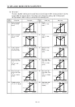
0C Feedback
position
(10 V ± 5 V/100
Mpulses)
100 [Mpulse]
100 [Mpulse]
CW direction
CCW direction
10 [V]
15 [V]
5 [V]
0
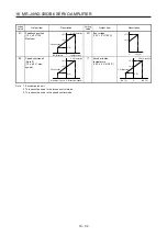
0D Bus
voltage
(10 V + 5 V/100 V)
100 [V]
10 [V]
15 [V]
0
0E
Speed command 2
(Note 2)
(10 V ± 4 V/ max.
speed)
Maximum speed
Maximum speed
CW direction
CCW direction
10 [V]
14 [V]
6 [V]
0
17 Encoder
inside
temperature
(10 V ± 5 V/±128 °C)
128 [°C]
-128 [°C]
CW direction
CCW direction
10 [V]
15 [V]
5 [V]
0
Note 1. Encoder pulse unit
2. This cannot be used in the torque control mode.
3. This cannot be used in the speed control mode.
Summary of Contents for MR-J4W2
Page 9: ...A 8 MEMO ...
Page 17: ...8 MEMO ...
Page 31: ...1 FUNCTIONS AND CONFIGURATION 1 14 MEMO ...
Page 95: ...4 STARTUP 4 20 MEMO ...
Page 169: ...6 NORMAL GAIN ADJUSTMENT 6 20 MEMO ...
Page 201: ...7 SPECIAL ADJUSTMENT FUNCTIONS 7 32 MEMO ...
Page 213: ...8 TROUBLESHOOTING 8 12 MEMO ...
Page 219: ...9 OUTLINE DRAWINGS 9 6 MEMO ...
Page 229: ...10 CHARACTERISTICS 10 10 MEMO ...
Page 295: ...13 USING STO FUNCTION 13 14 MEMO ...
Page 327: ...14 USING A LINEAR SERVO MOTOR 14 32 MEMO ...
Page 371: ...16 FULLY CLOSED LOOP SYSTEM 16 24 MEMO ...
Page 521: ...APPENDIX App 38 ...
Page 537: ...MEMO ...
Page 541: ......


