


7. SPECIAL ADJUSTMENT FUNCTIONS
7 - 30
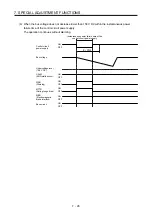
(3) Calculation of tolerance against instantaneous power failure
Table 7.2 shows tolerance against instantaneous power failure when instantaneous power failure
voltage is "rated voltage × 50%" and instantaneous power failure time is 200 ms.
Table 7.2 Tolerance against instantaneous power failure
(instantaneous power failure voltage = rated voltage × 50%,
instantaneous power failure time = 200 ms)
Servo amplifier model
Instantaneous
maximum output [W]
Tolerance against
instantaneous power
failure [W]
(Voltage drop
between lines)
MR-J4W2-22B
1400 (700
×
2)
790
MR-J4W2-44B
2800 (1400
×
2)
1190
MR-J4W2-77B
5250 (2625
×
2)
2300
MR-J4W2-1010B
6000 (3000
×
2)
2400
MR-J4W3-222B
2100 (700
×
3)
970
MR-J4W3-444B
4200 (1400
×
3)
1700
Instantaneous maximum output means power which servo amplifier can output in maximum torque at
rated speed. You can examine margins to compare the values of following conditions and instantaneous
maximum output.
Even if driving at maximum torque with low speed in actual operation, the motor will not drive with the
maximum output. This can be handled as a margin.
The following shows the conditions of tolerance against instantaneous power failure.
(a) Delta connection
For 3-phase (L1/L2/L3) delta connection, an instantaneous power failure will be applied to a voltage
between lines (e.g. between L1 and L2) from three pairs of voltages between lines (between L1 and
L2, L2 and L3, or L3 and L1).
(b) Star connection
For 3-phase (L1/L2/L3/neutral point N) star connection, an instantaneous power failure will be
applied to a voltage between lines (e.g. between L1 and N) from six pairs of voltages between lines
(between L1 and L2, L2 and L3, or L3 and L1) and between line and neutral point (between L1 and
N, L2 and N, or L3 and N).
Summary of Contents for MR-J4W2
Page 9: ...A 8 MEMO ...
Page 17: ...8 MEMO ...
Page 31: ...1 FUNCTIONS AND CONFIGURATION 1 14 MEMO ...
Page 95: ...4 STARTUP 4 20 MEMO ...
Page 169: ...6 NORMAL GAIN ADJUSTMENT 6 20 MEMO ...
Page 201: ...7 SPECIAL ADJUSTMENT FUNCTIONS 7 32 MEMO ...
Page 213: ...8 TROUBLESHOOTING 8 12 MEMO ...
Page 219: ...9 OUTLINE DRAWINGS 9 6 MEMO ...
Page 229: ...10 CHARACTERISTICS 10 10 MEMO ...
Page 295: ...13 USING STO FUNCTION 13 14 MEMO ...
Page 327: ...14 USING A LINEAR SERVO MOTOR 14 32 MEMO ...
Page 371: ...16 FULLY CLOSED LOOP SYSTEM 16 24 MEMO ...
Page 521: ...APPENDIX App 38 ...
Page 537: ...MEMO ...
Page 541: ......