17. APPLICATION OF FUNCTIONS
17 - 2
17.1.2 Operation modes supported by J3 compatibility mode
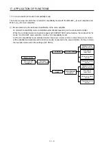
The J3 compatibility mode supports the following operation modes.
Operation mode in J3 compatibility mode
Model of MR-J3-_B
Model of MR-J3-_BS Model of MR-J3W-_B
MR-J3-B standard control mode (rotary servo motor)
MR-J3-_B
MR-J3-_BS
MR-J3W-_B
MR-J3-B fully closed loop control mode MR-J3-_B-RJ006
MR-J3-_BS
MR-J3-B linear control mode
MR-J3-_B-RJ004 MR-J3W-_B
MR-J3-B DD motor control mode
MR-J3-_B-RJ080W
MR-J3W-_B
Each operation mode has the same ordering as conventional MR-J3-B series servo amplifiers and is
compatible with their settings.
In addition, the control response characteristic in the J3 compatibility mode will be the same as that of MR-J3
series.
17.1.3 J3 compatibility mode supported function list
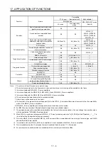
The following shows functions which compatible with J4 mode and J3 compatibility mode. The letters such
as "A0" described after and mean servo amplifier software versions which compatible with each
function. Each function is used with servo amplifiers with these software versions or later.
Compatible
( : J4 new, : Equivalent to J3, : Not available)
Function Name
MR-J4
series
MR-J3/MR-J3W series
(Note 8)
J4
mode
J3 compatibility
mode
Basic specification
Speed frequency response
2.5 kHz
2.1 kHz
2.1 kHz
Encoder resolution
22 bits (Note 1)
18 bits (Note 1)
18 bits
SSCNET III/H
communication or
SSCNET III
communication
Communication baud rate
150 Mbps
50 Mbps
50 Mbps
Maximum distance between stations
100 m
50 m
50 m
Basic function
Absolute position detection system
A0
A0
Fully closed loop control (Note 9)
A3
(Two-wire type only)
(Note 13)
A3
(Two-wire type only)
(Note 13)
MR-J3-_B-RJ006
MR-J3-_S
Linear servo motor driving
A0
(Two-wire type/
four-wire type only)
(Note 13)
A0
(Two-wire type/
four-wire type only)
(Note 13)
MR-J3-_B-RJ004
MR-J3W-_B
Direct drive motor driving
A0
A0
MR-J3-_B-RJ080W
MR-J3W-_B
Motor-less operation
A0 (Note 2)
A0 (Note 2)
Rotation direction selection/travel
direction selection
A0
A0
Encoder output pulses
A/B-phase pulse output
A0 (Note 3)
A0 (Note 3)
Z-phase pulse output
A0 (Note 4)
A0 (Note 4)
(Note 4)
Input/output
Analog monitor output
A0 (Note 5)
A0 (Note 5)
Motor thermistor
A0
A0
MR-J3-_B-RJ004
MR-J3-_B-RJ080W
MR-J3W-_B
Position control mode
A0
A0
Speed control mode
A0
A0
Control mode
Torque control mode
A0
A0
Continuous operation to torque
control mode
A0
A0
Summary of Contents for MR-J4W2
Page 9: ...A 8 MEMO ...
Page 17: ...8 MEMO ...
Page 31: ...1 FUNCTIONS AND CONFIGURATION 1 14 MEMO ...
Page 95: ...4 STARTUP 4 20 MEMO ...
Page 169: ...6 NORMAL GAIN ADJUSTMENT 6 20 MEMO ...
Page 201: ...7 SPECIAL ADJUSTMENT FUNCTIONS 7 32 MEMO ...
Page 213: ...8 TROUBLESHOOTING 8 12 MEMO ...
Page 219: ...9 OUTLINE DRAWINGS 9 6 MEMO ...
Page 229: ...10 CHARACTERISTICS 10 10 MEMO ...
Page 295: ...13 USING STO FUNCTION 13 14 MEMO ...
Page 327: ...14 USING A LINEAR SERVO MOTOR 14 32 MEMO ...
Page 371: ...16 FULLY CLOSED LOOP SYSTEM 16 24 MEMO ...
Page 521: ...APPENDIX App 38 ...
Page 537: ...MEMO ...
Page 541: ......

