18. MR-J4W2-0303B6 SERVO AMPLIFIER
18 - 22
18.3.3 Selection of main circuit power supply/control circuit power supply
The inrush current at power on will be large because a resistance for protecting inrush current is not built-in
in the main circuit power supply of the servo amplifier. The electric capacity of the main circuit capacitor is
approximately 630
μ
F. When the load characteristic (overcurrent protection criteria) of the power unit is
current fold back method, the power cannot be started. Be careful when selecting a power. Especially when
the power is turned ON/OFF on the power unit output side, approximately 100
μ
s to 300
μ
s instantaneous
current will flowed at power on due to capacitor charge. Therefore, a power unit such as one which operates
overcurrent at 1ms or less cannot be used.
A circuit to protect inrush current at power on is built-in in the control circuit power supply of servo amplifier.
In addition, when using main circuit power supply and control circuit power supply, use a reinforced
insulating type.
18.3.4 Power-on sequence
POINT
The voltage of analog monitor output, output signal, etc. may be unstable at
power-on.
(1) Power-on procedure
1) When wiring the power supply, use a circuit protector for the power supply (24/PM). Configure up
an external sequence so that the relay connected to PM turns off when an alarm occurs in both
axes of A and B.
2) Switch on the control circuit power supply (24/0) simultaneously with the main circuit power
supply (PM/0) or before switching on the main circuit power supply. If the control circuit power
supply is turned on with the main circuit power supply off, and then the servo-on command is
transmitted, [AL. E9 Main circuit off warning] will occur. Turning on the main circuit power supply
stops the warning and starts the normal operation.
3) The servo amplifier receives the servo-on command within 4 s after the main circuit power supply
is switched on.
(Refer to (2) of this section.)
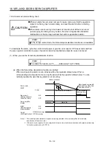
(2) Timing chart
Servo-on command accepted
Main circuit
Control circuit
Base circuit
Servo-on command
(from controller)
power supply
95 ms
(4 s)
95 ms
10 ms
ON
OFF
ON
OFF
ON
OFF
Summary of Contents for MR-J4W2
Page 9: ...A 8 MEMO ...
Page 17: ...8 MEMO ...
Page 31: ...1 FUNCTIONS AND CONFIGURATION 1 14 MEMO ...
Page 95: ...4 STARTUP 4 20 MEMO ...
Page 169: ...6 NORMAL GAIN ADJUSTMENT 6 20 MEMO ...
Page 201: ...7 SPECIAL ADJUSTMENT FUNCTIONS 7 32 MEMO ...
Page 213: ...8 TROUBLESHOOTING 8 12 MEMO ...
Page 219: ...9 OUTLINE DRAWINGS 9 6 MEMO ...
Page 229: ...10 CHARACTERISTICS 10 10 MEMO ...
Page 295: ...13 USING STO FUNCTION 13 14 MEMO ...
Page 327: ...14 USING A LINEAR SERVO MOTOR 14 32 MEMO ...
Page 371: ...16 FULLY CLOSED LOOP SYSTEM 16 24 MEMO ...
Page 521: ...APPENDIX App 38 ...
Page 537: ...MEMO ...
Page 541: ......


