8. TROUBLESHOOTING
8 - 10
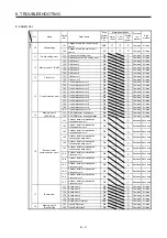
8.4 Troubleshooting at power on
When the servo system does not boot and system error occurs at power on of the servo system controller,
improper boot of the servo amplifier might be the cause. Check the display of the servo amplifier, and take
actions according to this section.
Display Description
Cause
Checkpoint
Action
AA
Communication with the
servo system controller
has disconnected.
The power of the servo
system controller was
turned off.
Check the power of the servo
system controller.
Switch on the power of the servo
system controller.
SSCNET III cable was
disconnected.
"AA" is displayed in the
corresponding axis and following
axes.
Replace the SSCNET III cable of
the corresponding axis.
Check if the connectors (CNIA,
CNIB) are unplugged.
Connect correctly.
The power of the servo
amplifier was turned off.
"AA" is displayed in the
corresponding axis and following
axes.
Check the power of the servo
amplifier.
Replace the servo amplifier of the
corresponding axis.
Ab Initialization
communication with the
servo system controller
has not completed.
All axes are in a state of
disabling control axis.
Check if the disabling control axis
switches (SW2-2, 2-3, and 2-4)
are on.
Turn off the disabling control axis
switches (SW2-2, 2-3, and 2-4).
Axis No. is set incorrectly. Check that the other servo
amplifier is not assigned to the
same axis No.
Set it correctly.
Axis No. does not match
with the axis No. set to
the servo system
controller.
Check the setting and axis No. of
the servo system controller.
Set it correctly.
Information about the
servo series has not set
in the simple motion
module.
Check the value set in Servo
series (Pr.100) in the simple
motion module.
Set it correctly.
Communication
cycle
does not match.
Check the communication cycle
at the servo system controller
side.
When using 8 axes or less:
0.222 ms
When using 16 axes or less:
0.444 ms
When using 32 axes or less:
0.888 ms
Set it correctly.
Connection to MR-J4W3-
_B with software version
A2 or earlier was
attempted in 0.222 ms
communication cycle.
Check if the communication cycle
on servo system controller side is
0.222 ms.
Use them with 0.444 ms or more
communication cycle.
SSCNET III cable was
disconnected.
"Ab" is displayed in the
corresponding axis and following
axes.
Replace the SSCNET III cable of
the corresponding axis.
Check if the connectors (CNIA,
CNIB) are unplugged.
Connect correctly.
The power of the servo
amplifier was turned off.
"Ab" is displayed in an axis and
the following axes.
Check the power of the servo
amplifier.
The servo amplifier is
malfunctioning.
"Ab" is displayed in an axis and
the following axes.
Replace the servo amplifier of the
corresponding axis.
Summary of Contents for MR-J4W2
Page 9: ...A 8 MEMO ...
Page 17: ...8 MEMO ...
Page 31: ...1 FUNCTIONS AND CONFIGURATION 1 14 MEMO ...
Page 95: ...4 STARTUP 4 20 MEMO ...
Page 169: ...6 NORMAL GAIN ADJUSTMENT 6 20 MEMO ...
Page 201: ...7 SPECIAL ADJUSTMENT FUNCTIONS 7 32 MEMO ...
Page 213: ...8 TROUBLESHOOTING 8 12 MEMO ...
Page 219: ...9 OUTLINE DRAWINGS 9 6 MEMO ...
Page 229: ...10 CHARACTERISTICS 10 10 MEMO ...
Page 295: ...13 USING STO FUNCTION 13 14 MEMO ...
Page 327: ...14 USING A LINEAR SERVO MOTOR 14 32 MEMO ...
Page 371: ...16 FULLY CLOSED LOOP SYSTEM 16 24 MEMO ...
Page 521: ...APPENDIX App 38 ...
Page 537: ...MEMO ...
Page 541: ......

