17. APPLICATION OF FUNCTIONS
17 - 23
No.
Symbol
Name and function
Initial
value
[unit]
Setting
range
Each/
common
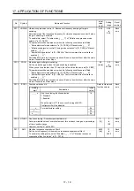
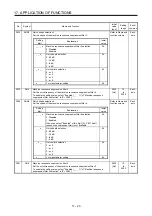
PX28
CVAT
SEMI-F47 function - Instantaneous power failure detection time
Set the time until the occurrence of [AL. 10.1 Voltage drop in the control circuit
power].
To disable the parameter, set "Disabled (_ 0 _ _)" of "SEMI-F47 function selection"
in [Pr. PX25].
200
[ms]
30
to
200
Common
PX29
DRAT
Drive recorder arbitrary alarm trigger setting
Refer to Name and
function column.
Common
Setting
digit
Explanation
Initial
value
_ _ x x
Alarm detail No. setting
Set the digits when you execute the trigger with arbitrary
alarm detail No. for the drive recorder function.
When these digits are "0 0", only the arbitrary alarm No.
setting will be enabled.
00h
x x _ _
Alarm No. setting
Set the digits when you execute the trigger with arbitrary
alarm No. for the drive recorder function.
When "0 0" are set, arbitrary alarm trigger of the drive
recorder will be disabled.
00h
Setting
example:
To activate the drive recorder when [AL. 50 Overload 1] occurs, set "5 0 0 0".
To activate the drive recorder when [AL. 50.3 Thermal overload error 4 during
operation] occurs, set "5 0 0 3".
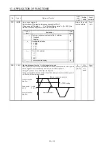
PX30
DRT
Drive recorder switching time setting
Set the drive recorder switching time.
When a USB communication is cut during using a graph function, the function will
be changed to the drive recorder function after the setting time of this parameter.
When a value from "1" to "32767" is set, it will switch after the setting value.
However, when "0" is set, it will switch after 600 s.
When "-1" is set, the drive recorder function is disabled.
0
[s]
-1
to
32767
Common
PX31
XOP4
Function selection X-4
Refer to Name and
function column.
Each
axis
Setting
digit
Explanation
Initial
value
_ _ _ x
Robust filter selection
0: Disabled
1: Enabled
When you select "Enabled" of this digit, the machine
resonance suppression filter 5 set in [Pr. PX22] is not
available.
0h
_ _ x _
For manufacturer setting
0h
_ x _ _
0h
x _ _ _
0h
Summary of Contents for MR-J4W2
Page 9: ...A 8 MEMO ...
Page 17: ...8 MEMO ...
Page 31: ...1 FUNCTIONS AND CONFIGURATION 1 14 MEMO ...
Page 95: ...4 STARTUP 4 20 MEMO ...
Page 169: ...6 NORMAL GAIN ADJUSTMENT 6 20 MEMO ...
Page 201: ...7 SPECIAL ADJUSTMENT FUNCTIONS 7 32 MEMO ...
Page 213: ...8 TROUBLESHOOTING 8 12 MEMO ...
Page 219: ...9 OUTLINE DRAWINGS 9 6 MEMO ...
Page 229: ...10 CHARACTERISTICS 10 10 MEMO ...
Page 295: ...13 USING STO FUNCTION 13 14 MEMO ...
Page 327: ...14 USING A LINEAR SERVO MOTOR 14 32 MEMO ...
Page 371: ...16 FULLY CLOSED LOOP SYSTEM 16 24 MEMO ...
Page 521: ...APPENDIX App 38 ...
Page 537: ...MEMO ...
Page 541: ......

