18. MR-J4W2-0303B6 SERVO AMPLIFIER
18 - 53
18.8.3 Selection example of wires
POINT
Refer to section 11.1.2 for SSCNET III cable.
To comply with the IEC/EN/UL/CSA standard, use the wires shown in appendix
4 for wiring. To comply with other standards, use a wire that is complied with
each standard.
Selection conditions of wire size are as follows.
Construction condition: Single wire set in midair
Wire length: 30 m or less
The voltage drops because of the cable conductor resistance. Especially for
main circuit/control circuit power supply wiring, wire to secure the required input
voltage at servo amplifier input section. It is recommended that the cable length
be as short as possible.
(1) Wires for power supply wiring
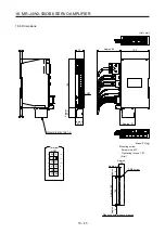
The following diagram shows the wires used for wiring. Use the wires or equivalent given in this section.
Servo amplifier
24
0
PM
1) Main/control circuit power supply lead
U1
V1
W1
2) Servo motor power lead
-
+
24 V DC
power supply
+
-
48 V DC
power supply
U2
V2
W2
E1
E2
M
M
The following shows the wire size selection example.
Table 18.4 Wire size selection example (HIV wire)
Servo amplifier
Wire [mm
2
]
1) 24/0/PM/
2) U1/V1/W1/E1
U2/V2/W2/E2
(Note)
MR-J4W2-0303B6
AWG 16
AWG 19
Note. The wire size shows applicable size of the servo amplifier connector. For wires
connecting to the servo motor, refer to "Servo Motor Instruction Manual (Vol. 3)".
Summary of Contents for MR-J4W2
Page 9: ...A 8 MEMO ...
Page 17: ...8 MEMO ...
Page 31: ...1 FUNCTIONS AND CONFIGURATION 1 14 MEMO ...
Page 95: ...4 STARTUP 4 20 MEMO ...
Page 169: ...6 NORMAL GAIN ADJUSTMENT 6 20 MEMO ...
Page 201: ...7 SPECIAL ADJUSTMENT FUNCTIONS 7 32 MEMO ...
Page 213: ...8 TROUBLESHOOTING 8 12 MEMO ...
Page 219: ...9 OUTLINE DRAWINGS 9 6 MEMO ...
Page 229: ...10 CHARACTERISTICS 10 10 MEMO ...
Page 295: ...13 USING STO FUNCTION 13 14 MEMO ...
Page 327: ...14 USING A LINEAR SERVO MOTOR 14 32 MEMO ...
Page 371: ...16 FULLY CLOSED LOOP SYSTEM 16 24 MEMO ...
Page 521: ...APPENDIX App 38 ...
Page 537: ...MEMO ...
Page 541: ......


