5. PARAMETERS
5 - 45
No.
Symbol
Name and function
Initial
value
[unit]
Setting
range
Each/
Common
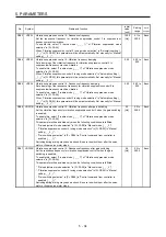
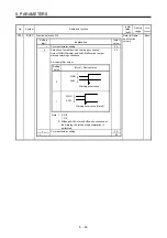
PD09
*DO3
Output device selection 3
You can assign any output device to the CN3-11 pin for each axis. CALM (AND
malfunction) is assigned to the all axes in the initial setting.
The devices that can be assigned and the setting method are the same as in [Pr.
PD07].
Refer to Name
and function
column.
Common
Setting
digit
Explanation
Initial
value
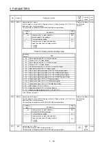
_ _ x x
Device selection
Refer to table 5.8 in [Pr. PD07] for settings.
03h
_ x _ _
All-axis output condition selection
0: AND output
When all axes of A, B, and C meet a condition, the
device will be enabled (on or off).
1: OR output
When each axis of A, B, or C meet a condition, the
device will be enabled (on or off).
The digit will be enabled when "All axes (0 _ _ _)" is
selected.
0h
x _ _ _
Output axis selection
0: All axes
1: A-axis
2: B-axis
3: C-axis
0h
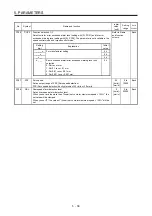
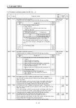
PD11
*DIF
Input filter setting
Select the input filter.
Refer to Name
and function
column.
Common
Setting
digit
Explanation
Initial
value
_ _ _ x
Input signal filter selection
Refer to the servo system controller instruction manual for
the setting.
If external input signal causes chattering due to noise, etc.,
input filter is used to suppress it.
0: None
1: 0.888 [ms]
2: 1.777 [ms]
3: 2.666 [ms]
4: 3.555 [ms]
4h
_ _ x _
For manufacturer setting
0h
_ x _ _
0h
x _ _ _
0h
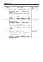
PD12
*DOP1 Function selection D-1
Refer to Name
and function
column.
Each
Setting
digit
Explanation
Initial
value
_ _ _ x
For manufacturer setting
0h
_ _ x _
0h
_ x _ _
0h
x _ _ _
Servo motor or linear servo motor thermistor enabled/
disabled selection
(Supported by servo amplifiers with software version A5 or
above.)
0: Enabled
1: Disabled
For servo motors or linear servo motor without thermistor,
the setting will be disabled.
0h
Summary of Contents for MR-J4W2
Page 9: ...A 8 MEMO ...
Page 17: ...8 MEMO ...
Page 31: ...1 FUNCTIONS AND CONFIGURATION 1 14 MEMO ...
Page 95: ...4 STARTUP 4 20 MEMO ...
Page 169: ...6 NORMAL GAIN ADJUSTMENT 6 20 MEMO ...
Page 201: ...7 SPECIAL ADJUSTMENT FUNCTIONS 7 32 MEMO ...
Page 213: ...8 TROUBLESHOOTING 8 12 MEMO ...
Page 219: ...9 OUTLINE DRAWINGS 9 6 MEMO ...
Page 229: ...10 CHARACTERISTICS 10 10 MEMO ...
Page 295: ...13 USING STO FUNCTION 13 14 MEMO ...
Page 327: ...14 USING A LINEAR SERVO MOTOR 14 32 MEMO ...
Page 371: ...16 FULLY CLOSED LOOP SYSTEM 16 24 MEMO ...
Page 521: ...APPENDIX App 38 ...
Page 537: ...MEMO ...
Page 541: ......


