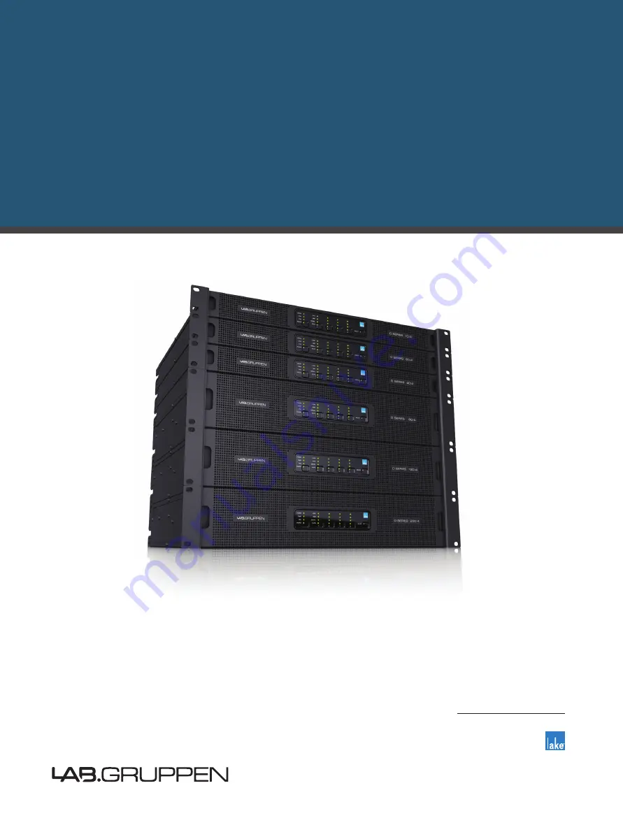
D SERIES
High-Power installation
platform
Rev. 3.0.4
Quick Start Guide
Lake Variants:
D 200:4LD 120:4L
D 80:4L
D 40:4L
D 20:4L
D 10:4L
Incorporating technologies from
Item no. QSG-DSERIES-LAKE
Page 1: ...DSERIES High Powerinstallationplatform Rev 3 0 4 Quick Start Guide Lake Variants D 200 4L D 120 4L D 80 4L D 40 4L D 20 4L D 10 4L Incorporating technologies from Item no QSG DSERIES LAKE...
Page 2: ...ING To reduce the risk of re or electric shock do not expose this apparatus to rain or moisture 17 Do not expose this equipment to dripping or splashing and ensure that no objects lled with liquids su...
Page 3: ...imits for the European Electro Magnetic Compatibility EMC directive This equipment has also been tested and found to comply with the limits for a Class A digital device pursuant to Part 15 of the FCC...
Page 4: ...3 Warnings 4 DSERIESLakeQuickStartGuiderev3 0 4 2014 30 EU EMC 2014 35 EU EN55103 1 E4 EN55103 2 E5...
Page 5: ...3 Warnings 5 DSERIESLakeQuickStartGuiderev3 0 4...
Page 6: ...nir le choc lectrique n enlevez pas les couvercles Il n y a pas des parties serviceable l int rieur tous reparations doit etre faire par personnel qualP seulment EMC European Electro Magnetic Com pati...
Page 7: ...st plac sur l appareil Fran ais Cet appareil doit tre raccord une prise secteur avec terre de protection Fran ais Lorsque la prise du r seau d alimentation est utilis s comme dispositif de d connexion...
Page 8: ...entation lectrique pour d brancher l appareil du secteur 16 AVERTISSEMENT pour r duire le risque d incendie et de choc lectrique n exposez pas cet appareil la pluie ni l humidit 17 N exposez pas cet a...
Page 9: ...d autres appareils tels que les radior cepteurs L absence d interf rences n est toutefois pas garantie pour une installation donn e Si cet quipement provoque des interf rences nuisibles la r ception...
Page 10: ...zu trennen 16 WARNUNG Um die Gefahr eines Feuers oder eines elektrischen Schlages zu verringern darf dieses Ger t nicht Regen oder starker Feuchtigkeit ausgesetzt werden 17 Setzen Sie dieses Ger t ni...
Page 11: ...ten der Federal Communications Commission FCC f r digitale Ger te der Klasse B nach Abschnitt 15 Diese Einschr nkungen sollen angemessenen Schutz vor sch dlichen St rungen durch elektrische Ger te gew...
Page 12: ...mita que este aparato quede expuesto a la lluvia o la humedad 17 No permita que este aparato quede expuesto a salpicaduras de ning n tipo y no coloque objetos que contengan l quidos como jarrones enci...
Page 13: ...ctiva europea de compatibilidad electromagn tica EMC Tambi n se ha veri cado que este aparato cumple con los l mites establecidos para dispositivos digitales de clase A de acuerdo a lo expuesto en el...
Page 14: ...ries Two versions available 16 6 Feature summary 17 6 1 Features unique to Lake variants 17 7 Installation 18 7 1 Unpacking 18 7 1 1 Included in the box 18 7 2 Mounting 18 7 2 1 Rear Mounting 18 7 2 2...
Page 15: ...ogy 27 13 1 2 Network con guration 27 13 2 Software installation and rmware update 28 13 2 1 Lake Controller software suite 28 13 2 2 CAF software 28 13 2 3 Firmware update 28 13 3 System setup 29 13...
Page 16: ...ut models The six Lake power output models come in two form factors Three high power models in a standard form factor and three lower powered models in a slimline single rack unit form factor Thank yo...
Page 17: ...board DSP Tplifier gain is set in the digital domain and controlled via the Lake Controller software ISVPL The Inter Sample Voltage Peak Limiter ISVPL tailors each channel s power output to the charac...
Page 18: ...d dust lter assembly NOTE Depending on the model the connector kit might include more connectors than applicable for the product you have Select those connectors required for your unit and application...
Page 19: ...t grille adheres to the ampli er with magnets Hold the front grille with your ngers in each of the side cutouts and slide it gently into place straight from the front NOTE Always ensure the dust lters...
Page 20: ...ow will be drawing in air which has already been heated by the D Series devices The D Series device is equipped with a sophisticated temperature sensing system which protects it from any overheating w...
Page 21: ...A m p A m p 3 phase Y 120V 3 phase delta 208V 208V 2 0 8 V 2 0 8 V L1 L2 L3 Three phase delta con guration Connecting the ampli er in a split phase con guration In two phase split phase con guration...
Page 22: ...ply faults and unstable mains supply 6 POWER LED and TOUCH BUTTON Provides power state indication and control Press and hold button to toggle the ampli er between ON and STANDBY state LED indication g...
Page 23: ...LEDs 6 10 and 11 all buttons on the lowest row ash in amber when hitting any touch button The front panel can only be re enabled from the Lake Controller OFF Green Amber Red Frame N A Frame OK Frame...
Page 24: ...n amber LED to initiate the soft reset sequence c To cancel press channel 4 mute button green LED 4 Wait state indication is present while either reset is performed 5 To complete the factory reset pro...
Page 25: ...inal 2 Analog Inputs Analog inputs are available on terminal block connectors with clearly marked hot cold and ground terminals 3 AES3 Inputs AES3 inputs are available on terminal block connectors wit...
Page 26: ...lection and MUTE 2 Input Mixer Stage Router on off connection to mixer and gain settings 3 Module Input Stage Mute and gain settings 4 Module Output Stage Mute and gain settings 5 Output Router Stage...
Page 27: ...dio along with control data NOTE If using Dante audio in the network the audio traf c needs to be ltered from reaching the wireless links 13 1 2 Networkcon guration Frames are con gured by default to...
Page 28: ...es updating 1 Make sure all frames are powered on and connected through a wired network 2 Launch the Lake rmware update utility LakeUpdate exe 3 Select the appropriate product range 4 If more than one...
Page 29: ...button on the menu bar at the bottom of the screen to access the Module Menu and scroll bar 6 On the Module scroll bar the frame is represented with a frame containing four discs These are labeled A...
Page 30: ...the I O CONFIG screen displays a block diagram for the Modules Tapping the different blue blocks will access the con guration screens for Input mixer Levels Input EQ Delay and Output EQ Crossover res...
Page 31: ...and unmute the Module Input Mute Tap EQ Levels Exit to return to IO Con g 19 The left side of the IO con g screen holds frame con guration and summary for Clock con guration Input con guration Dante c...
Page 32: ...in area hit MODULES button select a module e g Module A tap I O Con g tap AMPLIFIER EVENTS CONTROL and navigate to the Control tab The CAF button next to bottom opens the CAF application and imports a...
Page 33: ...current sensing on amplimer output faulty Audio continues but protection might be compromised No load monitoring Restart device if not cleared it needs service Warning A D converter power supply fault...
Page 34: ...mains inlet Check mains distribution connection Fault Need service NEED SERVICE 1 8 Power supply internal error Restart device if not cleared it needs service Fault Mains voltage above 400 volt peak...
Page 35: ...reduce output power to avoid temperature becoming critical Warning D200 D120 D80 only Very high frequency warning VHF WARNING Amplimer channel gain reduction due to VHF content Check input signal Faul...
Page 36: ...B o c l a t i g i D t o l i P d a o L s i s y l a n a d n a n o i t a r e n e g e n o t t o l i P Load impedance analysis Yes L T P L T A n o i t a t i m i l n o o g t s u m w o h s d n a s n a f d e...
Page 37: ...NEMA 6 20P 250 V 20 A AS NZS 3112 230 V 15 A Aus Nz BS 546 230 V 16 A India C 30P 125V 30A Japan Power supply features A 8 x a M s e Y r e w o p h s u r n I t r a t s t f o S W 0 0 4 r e w o p s n i a...
Page 38: ...d 2 1 1 e g n a r c i m a n y D B d 0 7 z H k 1 t a k l a t s s o r C n o i t a r a p e s l e n n a h C Frequency response 1 W into 8 ohm 20 Hz 20 kHz 0 05 dB t floating point i b 2 3 z H k 6 9 h t a...
Page 39: ...t i l a n o i t c n u f t c e l e s e r a w t f o s e c i v e d l a n o i t c e r i d i b r o f D E L d n a n o t t u b h c u o T t c e l e S Mains Power z H 0 6 0 5 C A V 0 4 2 0 0 1 e g a t l o v l...
Page 40: ...is not covered by the warranty Units on which the serial number has been removed or defaced will not be eligible for warranty service Lab gruppen shall not be responsible for any incidental or conseq...
Page 41: ...Authorization number Please note for product return 1 Use the original packing 2 Include a copy of the sales receipt your name return address phone and fax number email address and description of the...
Page 42: ...PM R SMPS PFC CDM BEL UVL CAF ESP ISVPL Iso Float Raised Cosine MESA EQ LimiterMax and LoadLibrary are trademarks of Lab gruppen AB All other trademarks remain the property of their respective owners...