4. CiA402 Drive Profile
4-5
4.3
Position Control Modes
4.3.1
Cyclic Synchronous Position Mode
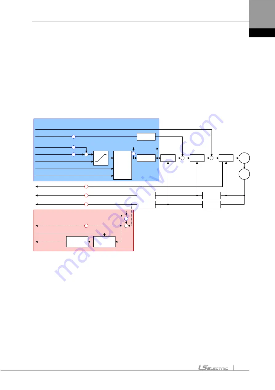
Cyclic Synchronous Position (CSP) mode receives the target position (0x607A) that is renewed at
every PDO update cycle from the upper level controller to control the position.
In this mode, the controller is able to calculate the velocity offset (0x60B1) and the torque offset
(0x60B2) that corresponds to the speed and torque feedforwards respectively, and pass them to the
drive.
The block diagram of CSP mode is as follows:
Torque Offset (0x60B2)
Velocity Offset (0x60B1)
Torque Actual Value (0x6077)
Position Offset (0x60B0)
Target Position (0x607A)
Software Position Limit (0x607D)
Quick Stop Deceleration (0x6085)
Quick Stop Option Code (0x605A)
Velocity Actual Value (0x606C)
Position Actual Value (0x6064)
Following Error Actual Value (0x60F4)
+
+
Interpolate
Position
Command
Gear Ratio
Position
Control
Velocity
Control
Torque
Control
+
+
+
+
M
Gear Ratio
Position Demand
Value (0x6062)
Enc.
Velocity
Calculation
Position
Calculation
Gear Ratio
Inverse
Gear Ratio
Inverse
Position Actual Internal
Value (0x6063)
Following Error Window (0x6065)
Following
Error Window
Comparator
Following
Error TimeOut
(0x6066)
Position Demand
Value (0x6062)
C
+
-
Following Error in
Statusword (0x6041.13)
Following Error
Position Demand Internal
Value (0x60FC)
OP Mode : Cyclic Synchronous Position
3
2
1
6
7
8
9
C
Summary of Contents for L7NHF Series
Page 2: ......
Page 14: ...Table of Contents xii ...
Page 60: ...2 Wiring and Connection 2 38 ...
Page 158: ...6 Safety Functions 6 6 ...
Page 172: ...7 Tuning 7 14 ...
Page 182: ...8 Procedure Function 8 10 ...
Page 192: ...9 Full Closed Control 9 10 ...
Page 214: ...10 Object Dictionary 10 22 ...
Page 363: ...11 Product Specifications 11 43 ...
Page 364: ......


