background image

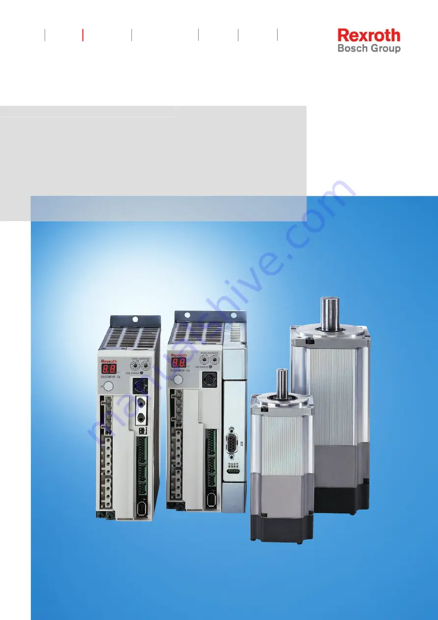
Rexroth IndraControl VCP 20

Industrial

Hydraulics

Electric Drives

and Controls 

Linear Motion and 

Assembly Technologies

Pneumatics

Service

Automation

Mobile

Hydraulics

Rexroth EcoDrive Cs

Drives

R911295758

Edition 02

Project Planning Manual

Courtesy 

of 

CMA/Flodyne/Hydradyne 

 Motion 

Control 

 Hydraulic 

 Pneumatic 

 Electrical 

 Mechanical 

 (800) 

426-5480 

 www.cmafh.com


Summary of Contents for EcoDrive Cs

Page 1: ...Linear Motion and Assembly Technologies Pneumatics Service Automation Mobile Hydraulics Rexroth EcoDrive Cs Drives R911295758 Edition 02 Project Planning Manual Courtesy of CMA Flodyne Hydradyne Motio...

Page 2: ...f the grant of a patent or the registration of a utility model or design DIN 34 1 The specified data only serve to describe the product No statements concerning a certain condition or suitability for...

Page 3: ...1 3 3 Hazards by Improper Use 3 2 3 4 General Information 3 3 3 5 Protection Against Contact with Electrical Parts 3 5 3 6 Protection Against Electric Shock by Protective Low Voltage PELV 3 6 3 7 Prot...

Page 4: ...Motor 5 9 Ground Connection 5 11 X4 Encoder 5 12 X5_1 Digital Inputs 5 13 X5_2 Digital Outputs 5 15 X5_3 Holding Brake 5 18 X6 Serial Interface RS232 5 21 5 2 Connections Dependent on the Device 5 23...

Page 5: ...gning the Control Cabinet 7 1 7 1 Notes on Control Cabinet Project Planning 7 1 Mounting Position and Distances 7 1 Arranging the Components in the Control Cabinet 7 3 7 2 Using Cooling Units in the C...

Page 6: ...cal Personnel 8 40 Mounting the Motor 8 40 Connecting the Motor 8 41 8 10 Startup Operation and Maintenance 8 42 Startup 8 42 Operation 8 43 Maintenance 8 43 9 Identifying the Components 9 1 9 1 Marki...

Page 7: ...nstallation dimensions 10 27 Front views 10 27 Electrical connection 10 28 Type code 10 29 10 5 DST transformers 10 30 Selection 10 30 Autotransformers for Drive Controllers 10 30 Technical Data 10 31...

Page 8: ...VI Contents Rexroth EcoDrive Cs Drives DOK ECODR3 DKC 3 CS PR02 EN P Courtesy of CMA Flodyne Hydradyne Motion Control Hydraulic Pneumatic Electrical Mechanical 800 426 5480 www cmafh com...

Page 9: ...d for use in systems with multiple axis devices and can also be used as intelligent single axes on a standard field bus There are four motor sizes 100 W 200 W 400 W 750 W with minimum dimensions that...

Page 10: ...terized by the configuration of the basic device with the respective master communication card There are the following end devices End device Basic device Master communication card Master communicatio...

Page 11: ...DN01 DKC10 3 DN02 DKC02 3 xxx DKC01 3 xxx DKC03 3 xxx DKC05 3 xxx DKC06 3 xxx DKC16 3 xxx DKC10 3 xxx analog parallel parallel Fig 1 2 Overview Note Given the respective configuration of the digital...

Page 12: ...ake 200 W absolute plain shaft without brake 200 W absolute plain shaft with brake 200 W absolute key without brake 200 W absolute key with brake DKCxx x 012 MSM030C 0300 NN C0 CG0 MSM030C 0300 NN C0...

Page 13: ...inal voltage 5 1 DC 300 V 3 6 Firmware 6 1 Multi interface general purpose MGP 7 Firmware version 7 1 e g 01 01 8 Nature of the firmware 8 1 Standard V 9 Firmware release status update 00 to 99 9 1 Re...

Page 14: ...version 7 1 e g 01 01 8 Nature of the firmware 8 1 Standard V 9 Firmware release status update 00 to 99 9 1 Release status the currently valid status status of the items list delivered RS Illustratio...

Page 15: ...e version 7 1 e g 01 01 8 Nature of the firmware 8 1 Standard V 9 Firmware release status update 00 to 99 9 1 Release status the currently valid status status of the items list delivered RS Illustrati...

Page 16: ...4 3 DeviceNet micro style DN02 4 4 none cover NNNN 4 5 PROFIBUS DB PB01 5 Other design 5 1 none NN Illustration example ECM01 1 1 2 3 4 6 7 8 9 1 0 5 1 2 3 4 6 7 8 9 2 0 5 1 2 3 4 6 7 8 9 3 0 5 1 2 3...

Page 17: ...sulting from inappropriate use are forfeited The user alone carries all responsibility of the risks Before using Rexroth products make sure that all the pre requisites for an appropriate use of the pr...

Page 18: ...are available with differing drive power and different interfaces Typical applications of drive controllers are handling and mounting systems packaging and foodstuff machines printing and paper proce...

Page 19: ...his equipment If the equipment is resold rented or transferred or passed on to others then these safety instructions must be delivered with the equipment WARNING Improper use of this equipment failure...

Page 20: ...ons Danger to life or bodily harm by electric shock WARNING Health hazard for persons with heart pacemakers metal implants and hearing aids in proximity to electrical equipment CAUTION Surface of mach...

Page 21: ...l safety regulations and requirements for the specific application as practiced in the country of use The equipment is designed for installation in industrial machinery The ambient conditions given in...

Page 22: ...irements can be found in the documentation EMC in Drive and Control Systems The machine or installation manufacturer is responsible for compliance with the limiting values as prescribed in the nationa...

Page 23: ...e is not permanently connected to the points of the components provided for this purpose Before working with electrical parts with voltage higher than 50 V the equipment must be disconnected from the...

Page 24: ...ef tests always connect the protective conductor or connect with ground wire Otherwise high voltages can occur on the housing that lead to electric shock 3 6 Protection Against Electric Shock by Prote...

Page 25: ...can occur immediately after equipment is switched on or even after an unspecified time of trouble free operation The monitoring in the drive components will normally be sufficient to avoid faulty ope...

Page 26: ...possibility of loose parts flying off Mount the emergency stop switch in the immediate reach of the operator Verify that the emergency stop works before startup Don t operate the machine if the emerg...

Page 27: ...nt a serious health hazard to persons with heart pacemakers metal implants and hearing aids WARNING Health hazard for persons with heart pacemakers metal implants and hearing aids in proximity to elec...

Page 28: ...mounting of parts and components may cause injuries CAUTION Risk of injury by incorrect handling Bodily harm caused by crushing shearing cutting and mechanical shock Observe general installation and s...

Page 29: ...oject Planning Manual must be provided with pressurized media such as compressed air hydraulic oil cooling fluid and cooling lubricant supplied by external systems Incorrect handling of the supply and...

Page 30: ...tions for Electric Drives and Controls Rexroth EcoDrive Cs Drives DOK ECODR3 DKC 3 CS PR02 EN P Notes Courtesy of CMA Flodyne Hydradyne Motion Control Hydraulic Pneumatic Electrical Mechanical 800 426...

Page 31: ...0 333 3Hz 750W 123456 Made in Japan Rexroth Indramat GmbH DKC02 3 001 3 MGP 01VRS E164620 QR R Design notice Do not touch termi n al s wi t hi n 10 mi n utes after di s connect the power Ri s k of el...

Page 32: ...tection Do not touch heatsi n k when power i s ON Ri s k of burn Hazardous Voltage High Temperature Do not touch termi n al s wi t hi n 10 mi n utes after di s connect the power Ri s k of el e ctri c...

Page 33: ...eatsi n k when power i s ON Ri s k of burn Read the manual and follow the safety instructions before use Where residual current operated protective device RCD is used for protection in case of direct...

Page 34: ...Read the manual and follow the safety instructions before use Where residual current operated protective device RCD is used for protection in case of direct or indirect contact only RCD of Type B is a...

Page 35: ...and Wire Size Refer to Manual for Over Load Protection Do not touch heatsink when power is ON Risk of burn Hazardous Voltage High Temperature Do not touch terminals within 10 minutes after disconnect...

Page 36: ...mbol Unit DKC 3 004 DKC 3 008 DKC 3 012 DKC 3 018 mass SERCOS Analog Parallel 1 4 1 4 1 4 1 7 PROFIBUS DeviceNet CANopen m kg 1 8 1 8 1 8 2 1 materials used free of asbestos and silicone Fig 4 6 Mass...

Page 37: ...ion according to EN 60068 2 6 Amplitude and frequency Acceleration and frequency Tolerance 0 15 mm peak peak at 10 57 Hz 1 g at 57 150 Hz 15 Vibration distortion Random in operation according to IEC 6...

Page 38: ...For this reason before using the respective material a compatibility test has to be carried out for new lubricants cleaning agents etc and our housings our housing materials Courtesy of CMA Flodyne H...

Page 39: ...t resistor PDC Start W 17 switching frequency selectable fS kHz 4 and 8 continuous output current Iout_eff cont2 A 004 1 0 008 1 6 012 2 5 018 3 4 004 1 0 008 1 6 012 2 5 018 4 3 characteristic curve...

Page 40: ...54 008 018 0 81 DC bus voltage depending on mains input voltage UDC V 152 420 continuous DC bus power at 3 x AC 220 V at Ta 40 C PDC W 004 140 008 253 012 457 018 796 DC bus peak power PDCpeak W 004...

Page 41: ...ollowing performance data apply under the following conditions ambient temperature 40 C installation altitude 1000 m The braking resistor installed in the drive controller is not active because an ext...

Page 42: ...ltiplied The installation altitude must only be taken into account once deviating ambient temperatures must be taken into account separately for motor and drive controller According to restrictions of...

Page 43: ...on altitude of 1000 m three phase operation are kept Using the internal braking resistor causes additional power dissipation heat in the drive controller and derating 200 W and 400 W drive controllers...

Page 44: ...ce life of the drive controllers significant ecocs_derating_750 FH7 0 7 0 8 1 200 170 264 power supply voltage in V load factor Fig 4 14 Derating with single phase operation 750 W devices With 100 200...

Page 45: ...7 5 at AC 264 V 240 V 10 max input capacitance CN3 mF 0 039 power consumption at X1 at UN 200 V PN3 W SERCOS Drive 8 6 basic device 7 2 basic device SERCOS 8 8 basic device DeviceNet 8 6 basic device...

Page 46: ...e bootstrap loader firmware update With baud rate scan button for activating the manual mode Commissioning During baud rate scan press button for at least 5 seconds to get into the setting mode S2 S3...

Page 47: ...r the item Rexroth High voltage test in accordance with EN50178 Insulation voltage test in accordance with EN50178s Separation between control and power voltage circuits in accordance with EN50178 Air...

Page 48: ...nical Data Drive Controllers Rexroth EcoDrive Cs Drives DOK ECODR3 DKC 3 CS PR02 EN P Notes Courtesy of CMA Flodyne Hydradyne Motion Control Hydraulic Pneumatic Electrical Mechanical 800 426 5480 www...

Page 49: ...NPUT 200V 240V X3 X2 X1 X6 W V U RB2 RB3 RB1 DL2 DL1 L2C L1C L3 L2 L1 9 8 7 6 5 4 3 2 1 9 8 7 6 5 4 3 2 1 0 0 Fig 5 1 Front view with terminal connector designations Description of connections Connect...

Page 50: ...IN5 IN4 IN3 IN2 IN1 Bb2 Bb1 OUT7 OUT8 0V_ext 24V_ext TX RX S20 2 1 ON X4 X5 X6 ADDRESS NODE Rexroth ECODRIVE Cs S1 H1 S2 S3 LINE ERROR X20 X21 X4 X5_3 X5_2 X5_1 INPUT F200V 240V X3 X2 X1 X6 W V U RB2...

Page 51: ...X3 X2 X1 X6 braking resistor RS232 master communication encoder cable motor cable L1 L2 L3 L1C L2C RB1 RB2 U 0V W Ground Shield voltage supply of holding brake 24V BR BR V trans former L1 L2 L3 L1 N...

Page 52: ...ized externally The holding brake is connected at the X5_3 interface see page 5 18 Data for the holding brake see chapter Holding Brake on page 8 29 encoder cable If a motor with encoder is used an en...

Page 53: ...ittstellen_X1 fh7 TX RX S20 2 1 ON X4 X5 X6 W V U RB2 RB3 RB1 DL2 DL1 9 8 7 6 5 4 3 2 1 9 8 7 6 5 4 3 2 1 ADDRESS NODE 0 0 Rexroth ECODRIVE Cs S1 H1 S2 S3 LINE ERROR X20 X21 X4 X5_3 X5_2 X5_1 INPUT F2...

Page 54: ...1 S2 S3 LINE ERROR X20 X21 X4 X5_3 X5_2 X5_1 INPUT F200V 240V X3 X2 X1 X6 DL1 DL2 RB1 RB3 RB2 Fig 5 9 Terminal connector X2 Type Number of poles Type of design spring tension 5 socket on connector Fig...

Page 55: ...here isn t any choke used these connections must be jumpered A wire bridge is supplied together with the device Note Rexroth doesn t deliver additional chokes for Rexroth EcoDrive Cs drives device ext...

Page 56: ...iveTop by menu item Drive Functions Drive controller An external braking resistor is available as an accessory Data for the internal braking resistor see chapter 4 4 Electrical Data device external de...

Page 57: ...Technical Data of the Terminal Connector schnittstellen_X3 fh7 TX RX S20 2 1 ON X4 X5 X6 9 8 7 6 5 4 3 2 1 9 8 7 6 5 4 3 2 1 ADDRESS NODE 0 0 Rexroth ECODRIVE Cs S1 H1 S2 S3 LINE ERROR X20 X21 X4 X5_...

Page 58: ...ade Rexroth cable ambient temperature of 40 C according to EN 60204 maximum switching frequency of 8 kHz WARNING No warranty If cables manufactured by a company other than Bosch Rexroth resp cables lo...

Page 59: ...nd Fig 5 18 Ground connection Type Number Type of design terminal block 2 threaded terminal end for M4 ring cable lugs Fig 5 19 Design Cross section single core mm Max cross section in AWG gauge No 2...

Page 60: ...2 encoder voltage supply output 0V 3 positive pole of battery 4 negative pole of battery 5 encoder signal input PS 6 encoder signal input PS negated battery not required if the absolute encoder is us...

Page 61: ...tor X5_1 Type Number of poles Type of design spring tension 10 socket on connector Fig 5 25 Design Cross section single core mm Cross section in AWG gauge No 0 25 0 5 23 20 Fig 5 26 Connection cross s...

Page 62: ...tal inputs are galvanically separated the reference conductor of the separate power supply unit has to be connected to GND X5_1_dig_ein_prinzip fh7 R1 5V6 0 Vext R1 R3 R2 C1 C1 R1 1k R2 10k R3 4k7 C1...

Page 63: ...single core mm Cross section in AWG gauge No 0 25 0 5 23 20 Fig 5 32 Connection cross section Note The digital outputs can be configured by means of the Digital outputs firmware function in conjunctio...

Page 64: ...s 40 s 70 s 6 s overload protection short circuit proof electrical isolation optocoupler Fig 5 35 Technical Data Bb1 Bb2 Relais_Bb1_Bb2 fh7 12V GND Bb1 Bb2 Abb 5 36 Bb1 Bb2 relay max switching voltag...

Page 65: ...parameterization see firmware Functional Description Power off on error How to use the contact see page 6 17 WARNING Damage possible if Bb contact not connected The ready to operate contact Bb acknowl...

Page 66: ...r by for example mechanically blocking the vertical axis adding an external braking catching clamping mechanism or providing sufficient counterbalance for the axis Switching performance see Functional...

Page 67: ...ge connection for brake Note The motor holding brake is not supplied by the drive controller Observe the data of the motor holding brake Note It is impossible to loop through the voltages to other dri...

Page 68: ...ne routing parallel where possible twist max inductance between 24 V source and X5_3 100 H corresponds to approx 2 x 75 m The drive controller assumes the control of the holding brake Line for Voltage...

Page 69: ...H1 S2 S3 LINE ERROR X20 X21 X4 X5_3 X5_2 X5_1 INPUT F200V 240V X3 X2 X1 X6 PS2_stecker_ecocs fh7 1 2 5 4 3 6 7 8 TxD GND RxD Fig 5 41 Terminal connector X6 Type Number of poles Type of design MiniDIN...

Page 70: ...5 44 Connecting a PC to the RS232 interface number of nodes a maximum of 1 transmission distance a maximum of 15 m transmission rates 9600 and 19200 baud 8 bit ASCII protocol no parity bit 1 stop bit...

Page 71: ...V W 9 8 7 6 5 4 3 2 1 9 8 7 6 5 4 3 2 1 ADDRESS NODE 0 0 Rexroth ECODRIVE Cs S1 H1 S2 S3 LINE ERROR X4 X5_3 X5_2 X5_1 INPUT F200V 240V X3 X2 X1 X6 schnittstellen_X7_X54 fh7 ana_para_front FH7 X7 X5_4...

Page 72: ...0 input 7 IN9 input 6 IN8 input 5 OUT6 output 4 OUT5 output 3 OUT4 output 2 OUT3 output 1 OUT2 output Fig 5 48 Pin configuration Note Default configuration see Functional Description of firmware The i...

Page 73: ...Encoder emulation incremental IgsUA1 O 2 Encoder emulation incremental IgsUA1 O 3 Ground 0V Encoder emulation incremental IgsUA2 O 4 Encoder emulation SSI SSI CLK I Encoder emulation incremental IgsU...

Page 74: ...put and Fig 5 56 Output of absolute actual position value in SSI format double shield protected CAUTION Damaging potential by utilizing non and single shielded cables Utilize double shielded cables No...

Page 75: ...rential outputs Note The differential outputs correspond to RS422 specs A termination resistor is required an the controller side if it is not present then add an external resistance of 150 180 Ohm on...

Page 76: ...signal filtering for UA1 and UA2 arise f 500 kHz fPass 1 MHz f 500 kHz fPass 2 x f Note The evaluation electronics of the control must be able to process the maximum output frequency of 1 MHz Otherwi...

Page 77: ...resistance see circuit Pulse frequency 100 1000 kHz Polarity protected within allowable input voltage range Fig 5 58 Differential outputs See Fig 5 53 Differential outputs Note The differential outpu...

Page 78: ...22 1 Tp G23 G22 G0 PFB T m tv pulse break 20 s G0 G23 m T Tp tv PFB SV0202F1 FH7 resolution for 4096 rotations resolution for 1 rotations 1 2 25 24 data pulse Tp least significant bit in gray code mos...

Page 79: ...onnection assignment inputs outputs for DKC02 3 Switch sercos_schalter FH7 1 2 ON Fig 5 62 Switch for setting the transmission power The switch allows setting the transmission power for the SERCOS int...

Page 80: ...iber optic cables The data rate is automatically set by the firmware Fiber Optic Cables Drive controllers with a SERCOS interface are connected to higher level control units by means of fiber optic ca...

Page 81: ...1 5 9 Diagnostic indicators Profibus interface female 9 pins Fig 5 64 View of interface to master communication Technical Data of the Terminal Connector Type Number of poles Type of design D SUB 9 bu...

Page 82: ...70 according to DIN EN 50 170 2 cable type A Pin DIR Signal Function 1 n c 2 n c 3 I O RS485 receive transmit data positive 4 O CNTR P repeater control signal 5 0V 0V 6 O 5V repeater supply 7 n c 8 I...

Page 83: ...mA receive transmit data EIA RS485 standard Fig 5 69 Signal specification CAUTION Danger of destroying output 5V Repeater supply by overload do not short circuit do not exceed maximum current For the...

Page 84: ...d last bus node Carry out the connection as shown in the figures below AP5069f1 fh7 OFF ON OFF ON Bus connection and switch position for the first and last stations Bus connection and switch position...

Page 85: ...metal guide Fig 5 71 Bus connection for the first and last slave bus connector with 9 pin D SUB socket INS 0541 Siemens Siemens Ap5075f1 fh7 1 2 1 2 A B A B A B A B Siemens on off Siemens Terminating...

Page 86: ...s off The cable shield must be placed bare on the metal guide Fig 5 74 Bus connection for all other slaves without 9 pin D SUB socket INS 0540 Connect the drive controller to a control unit using a sh...

Page 87: ...62 H60 diagnostic indicators DeviceNet Interface male 5 pins 5 1 Fig 5 75 View of interface to master communication Technical Data of the Terminal Connector Type Number of poles Type of design COMBICO...

Page 88: ...l 3 shield shield connection 4 CAN differential signal 5 V interface supply Fig 5 79 Assignment of the interface signals 30 V Bus voltage Current consumption 11 V 70 mA 18 V 45 mA 24 V 35 mA 32 V 28 m...

Page 89: ...a Rate PGM 500 250 125 diagnostic indicators DeviceNet Interface X160 male 5 pins 5 1 2 4 3 switch data rate Fig 5 81 View of interface to master communication Technical Data of the Terminal Connector...

Page 90: ...inition 1 shield shield connection 2 V interface supply 3 V 0 V 4 CAN_H differential signal 5 CAN_L differential signal Fig 5 85 Assignment of the interface signals 30 V Bus voltage Current consumptio...

Page 91: ...50 9 5 1 6 Diagnostic indicators CANopen Interface male 9 pins Fig 5 87 View of interface to master communication Technical Data of the Terminal Connector Type Number of poles Type of design D SUB 9 p...

Page 92: ...hield shield connection 6 0V 0V 7 CAN_H differential signal 8 n c n c 9 n c n c Fig 5 91 Assignment of the interface signals Via D subminiature screws and metallized connector housing For the definiti...

Page 93: ...ping Brace fkm_transportsicherung fh7 FWA ECODR3 MGP 01VRS MS MadeinJapan 123456 K40 02 123456 F0001 SN123456 F0001 A15 X6 9 8 7 6 5 4 3 2 1 9 8 7 6 5 4 3 2 1 ADDRESS NODE 0 0 Rexroth ECODRIVE Cs S1 H...

Page 94: ...0001 SN123456 F0001 A15 X6 9 8 7 6 5 4 3 2 1 9 8 7 6 5 4 3 2 1 ADDRESS NODE 0 0 Rexroth ECODRIVE Cs S1 H1 S2 S3 LINEERROR X1 X2 X3 1 Carefully plug on master communication module at the drive controll...

Page 95: ...pa n 12 34 56 K 40 0 2 1 2 3 4 5 6 F 0 0 0 1 S N 1 2 3 4 5 6 F 0 0 0 1 A 1 5 X6 9 8 7 6 5 4 3 2 1 9 8 7 6 5 4 3 2 1 ADDRESS NODE 0 0 Rexroth ECODRIVE Cs S1 H1 S2 S3 LINEERROR X1 X2 X3 Fig 5 92 Screws...

Page 96: ...Electrical Connections Rexroth EcoDrive Cs Drives DOK ECODR3 DKC 3 CS PR02 EN P Notes Courtesy of CMA Flodyne Hydradyne Motion Control Hydraulic Pneumatic Electrical Mechanical 800 426 5480 www cmafh...

Page 97: ...and mains connection at the drive controller Observe the notes in the Safety Instructions for Electric Drives and Controls chapter Contents of the Chapter connection features kinds of connection sing...

Page 98: ...ion possible Mains and supply voltage connection have to be done via individual cables It is impossible to interconnect the DC buses and group or central supply is therefore impossible The control vol...

Page 99: ...Do not connect the drive controller directly to mains voltages higher than 240 V In the case of higher mains voltages the connection must be realized via a transformer 1 x AC min 200 V 15 170 V max 24...

Page 100: ...ax 240 V 10 264 V netzanschluss_3ph_m_spartrafo fh7 L1 L2 L3 L1C L2C K1 L1 L2 L3 T L1 L2 L3 mains T autotransformer only necessary when mains input voltage is higher than 240 V K1 magnetic contactor L...

Page 101: ...f DKC 3 004 100 W DKC 3 008 200 W DKC 3 012 400 W DKC 3 018 750 W Fig 6 6 Inrush current characteristic of DKC 3 008 200 W DKC 3 012 400 W DKC 3 018 750 W 0A 10A 20A 30A 40A 50A 60A 0 2 4 6 8 10 12 ti...

Page 102: ...ains input voltage IEIN 79 4 A total inrush current IEinGesamt 317 6 A Note This inrush current however is only of short duration because the time constant of the RC element with T RSoftstart x CZwisc...

Page 103: ...V max allowed mains input voltage IEIN 9 9 A for a single drive controller total inrush current IEinGesamt 39 6 A Ambient temperature 40 C R RSoftstart RNTC 4 7 Ohm 19 6 Ohm 24 3 Ohm UN1 264 V max all...

Page 104: ...trate the basic curve of the inrush current with completely discharged DC bus when switching on the mains voltage S t o p p e d 2 0 0 3 0 7 0 3 1 3 0 1 3 0 5 m s d i v 5 m s d i v N O R M 2 0 0 k S s...

Page 105: ...t C H 1 0 0 0 4 V C H 2 0 0 0 3 V C H 3 0 0 0 0 V C H 4 0 0 V R e c o r d L e n g t h M a i n 1 0 K Z o o m 1 0 K T r i g g er M o d e N O R M A L T yp e E D G E C H 1 D e l a y 0 0 n s H o l d o f f...

Page 106: ...4 1 0 0 m V D C 1 1 F i l t e r S m o ot h i n g O F F B W F U L L O f f s e t C H 1 0 0 0 4 V C H 2 0 0 0 3 V C H 3 0 0 V C H 4 0 0 0 0 V R e c o r d L e n g t h M ai n 1 0 K Z oo m 1 0 K T r i g g e...

Page 107: ...ote With multiple controllers add the individual powers and if necessary take a coincidence factor into account because often not all servo axes require full power simultaneously k 60 2 MITTEL EFF ZWD...

Page 108: ...for transformer F2 circuit breaker max 25 A F3 F4 fuse max 16 A when cross section is 1 5 mm 2 K1 mains contactor T1 transformer Fig 6 16 Mains connection with phase currents of more than 25 A Note D...

Page 109: ...former F2 circuit breaker max 25 A K1 mains contactor T1 transformer Fig 6 17 Mains connection with phase currents of less than 25 A Note Distribute the control voltage connections symmetrical to the...

Page 110: ...ax Maximum admissible mains input voltage Pmech Power at the driven shaft of the motor Efficiency PDC Continuous DC bus power SN1 Mains connection power IEin Inrush current IN1 Phase current of the ma...

Page 111: ...s has to be taken into account 6 drive controllers of the DKC0x 3 W0008 400 W type are to be operated with a mains filter The resulting total current is 6 5 3 A 31 8 A This means that the mains filter...

Page 112: ...00 61 140 3 400 2 436 0 9 78 6 200 71 253 2 700 2 471 1 6 78 6 400 83 457 1 1400 2 905 3 1 78 6 three phase 750 90 796 2 2400 2 848 5 3 78 6 Pmech Power at the driven shaft of the motor Efficiency PDC...

Page 113: ...e facility is protected via an overvoltage suppressor Note Connecting Rexroth EcoDrive Cs drive controllers via an isolating transformer offers the best protection against overvoltage as well as the g...

Page 114: ...nstallation and machine The ready to operate message is output via a relay contact N O If the Bb contact closes then the drive is ready to receive power The contact is thus a precondition for connecti...

Page 115: ...e fall delay time typically 80 150 ms of the mains contactor Control Circuits with E Stop Pre requisite Note The E stop input is available if the E stop function has been activated in the software and...

Page 116: ...stop for more drive controllers on same contactor 3 Switching power of Bb contact must be noted Fig 6 21 Example of generating the E stop signal Note Do not pick off the E Stop signal after the Bb co...

Page 117: ...he backs of the drive controllers on the mounting surface mounting plate of the control cabinet with all over contact Distances kuehlluft_ein_aus_mit_fronten fh7 L1 L2 L3 L1C L2C DL1 DL2 RB1 RB3 RB2 U...

Page 118: ...observe their max air inlet temperature see technical data and if necessary to mount air baffles with blowers used for this specific purpose For example air baffle Additional blower Discharge directi...

Page 119: ...hen cooling units are used For this reason please observe the following information Always position cooling units in such a way that condensation water cannot drip onto electronic equipment in the con...

Page 120: ...f the control cabinet is no lower than the temperature of the surrounding air Set the temperature limitation to the maximum surrounding temperature Only use well sealed control cabinets so that moistu...

Page 121: ...s are only to be used for producing installation connection diagrams The machine manufacturer s installation connection diagrams must be used for wiring the installation Lay signal lines separately fr...

Page 122: ...4 mm 100 mm Plastic cable duct Fig 7 5 Cable duct variants Note For details please see Project Planning Manual Electromagnetic Compatibility EMC in Drive and Control Systems document typecode DOK GENE...

Page 123: ...High performance data High dynamics owing to the favorable ratio of torque to inertia mass High overload capability owing to the favorable heat dissipation from the stator windings to the outside wall...

Page 124: ...1 Product 1 1 MSM MSM 2 Size 2 1 020 020 3 Length 3 1 Length B 4 Windings 4 1 MSM020B 0300 5 Cooling mode 5 1 natural convection without blower NN 6 Encoder 6 1 Incremental encoder C0 6 2 Multiturn a...

Page 125: ...nvection without blower NN 6 Encoder 6 1 Incremental encoder C0 6 2 Multiturn absolute encoder M0 7 Electrical connection 7 1 cable tail C 8 Shaft 8 1 key per DIN 6885 1 C 8 2 plain shaft G 9 Holding...

Page 126: ...encoder M0 7 Electrical connection 7 1 cable tail C 8 Shaft 8 1 key per DIN 6885 1 C 8 2 plain shaft G 9 Holding brake 9 1 without holding brake 0 9 2 electrical release 2 45 Nm 1 10 Standard referenc...

Page 127: ...x MSM030B 0300 NN M0 CG1 295554 x x x MSM030B 0300 NN M0 CC0 295570 x x x MSM030B 0300 NN M0 CC1 295571 x x x 200 W MSM030C MSM030C 0300 NN C0 CG0 295560 x x x MSM030C 0300 NN C0 CG1 295561 x x x MSM0...

Page 128: ...c curves specified correspond to the operating modes S1 or S6 t DtP DtV TC t P Qmax PV Q P Qmax PV Q Operating mode S6 Operating mode S1 P Load PV Electric losses Temperature max Highest temperature m...

Page 129: ...useful speed defined by the manufacturer Depending on the particular application other useful speeds are possible see speed torque curve Continuous torque that can be output at the rated speed in oper...

Page 130: ...r without the optional holding brake Unit kgm Motor mass without the optional holding brake and optional motor fan specified in kg Time of the temperature rise to 63 of the final temperature of the mo...

Page 131: ...coder 42 92 5 24 8 h6 22 h7 48 3 4 55 38 8 27 2 7 with brake with incremental encoder 42 124 0 24 8 h6 22 h7 48 3 4 55 38 8 27 2 7 without brake with absolute encoder 42 109 0 24 8 h6 22 h7 48 3 4 55...

Page 132: ...tor motor_kabel_m_g fh7 1 2 1 encoder cable 2 motor cable Fig 8 8 Cables at the motor Length of cables motor connector motor cable 200 mm 70 mm connector encoder cable 230 mm 62 mm connector See chapt...

Page 133: ...s 12 maximum speed nmax min 1 5000 motor mass 3 m kg 0 5 0 7 allowed storage and transport temp TL C 20 80 allowed ambient temperature 6 Tum C 0 40 max installation altitude 6 h m 1000 degree of prote...

Page 134: ...emperature 0 10 20 30 40 50 60 70 80 90 100 110 0 10 20 30 40 50 60 70 ambient temperature in C constant load in with reduced service life without reduced service life MSM020B 0300 NN ambient 30 C 0 0...

Page 135: ...der 60 96 0 30 11 h6 50 h7 70 4 5 73 34 0 27 3 7 with brake with incremental encoder 60 129 0 30 11 h6 50 h7 70 4 5 73 34 0 27 3 7 without brake with absolute encoder 60 111 0 30 11 h6 50 h7 70 4 5 73...

Page 136: ...or motor_kabel_m_g fh7 1 2 1 encoder cable 2 motor cable Fig 8 15 Cables at the motor Length of cables motor connector motor cable 200 mm 70 mm connector encoder cable 220 mm 62 mm connector See chapt...

Page 137: ...25 maximum speed nmax min 1 5000 motor mass 3 m kg 0 96 1 36 allowed storage and transport temp TL C 20 80 allowed ambient temperature 6 Tum C 0 40 max installation altitude 6 h m 1000 degree of prot...

Page 138: ...e ambient temperature 0 10 20 30 40 50 60 70 80 90 100 110 0 10 20 30 40 50 60 70 ambient temperature in C constant load in with reduced service life without reduced service life MSM030B 0300 NN ambie...

Page 139: ...der 60 123 5 30 14 h6 50 h7 70 4 5 73 61 5 27 3 7 with brake with incremental encoder 60 156 5 30 14 h6 50 h7 70 4 5 73 61 5 27 3 7 without brake with absolute encoder 60 138 5 30 14 h6 50 h7 70 4 5 7...

Page 140: ...or motor_kabel_m_g fh7 1 2 1 encoder cable 2 motor cable Fig 8 22 Cables at the motor Length of cables motor connector motor cable 200 mm 70 mm connector encoder cable 220 mm 62 mm connector See chapt...

Page 141: ...25 maximum speed nmax min 1 5000 motor mass 3 m kg 1 5 1 9 allowed storage and transport temp TL C 20 80 allowed ambient temperature 6 Tum C 0 40 max installation altitude 6 h m 1000 degree of protect...

Page 142: ...ed Fig 8 24 MSM030C torque characteristic Characteristic Torque Temperature Higher ambient temperatures cause a derating of the available torque Fig 8 25 MSM030C utilization depending on the ambient t...

Page 143: ...der 80 142 5 35 19 h6 70 h7 90 6 0 93 76 0 27 3 8 with brake with incremental encoder 80 176 5 35 19 h6 70 h7 90 6 0 93 76 0 27 3 8 without brake with absolute encoder 80 157 5 35 19 h6 70 h7 90 6 0 9...

Page 144: ...or motor_kabel_m_g fh7 1 2 1 encoder cable 2 motor cable Fig 8 29 Cables at the motor Length of cables motor connector motor cable 200 mm 70 mm connector encoder cable 220 mm 62 mm connector See chapt...

Page 145: ...s 50 maximum speed nmax min 1 4500 motor mass 3 m kg 3 1 3 8 allowed storage and transport temp TL C 20 80 allowed ambient temperature 6 Tum C 0 40 max installation altitude 6 h m 1000 degree of prote...

Page 146: ...the ambient temperature 0 10 20 30 40 50 60 70 80 90 100 110 0 10 20 30 40 50 60 70 ambient temperature in C constant load in with reduced service life without reduced service life MSM040B 0300 NN am...

Page 147: ...n of such attachments must be checked in isolated cases MSM motors if used stationary and weather resistant may be operated under the following conditions Longitudinal motor axis according to class 3M...

Page 148: ...rily immersed in water 5 Protection against a water jet from a nozzle directed against the housing from all directions jet water Fig 8 35 IP degrees of protection Tests regarding the second characteri...

Page 149: ...tup IM B5 Flange attached on the drive side of the flange IM V1 Flange attached on the drive side of the flange drive side pointing down IM V3 Flange attached on the drive side of the flange drive sid...

Page 150: ...in oil resistance according to standard JIS C 3005 the 20 th clause test conditions oil temperature 70 C test time cable in oil 4 hours oil machine oil 46 from GENERAL 2 aluminum anodized 3 rubber 4 d...

Page 151: ...according to the electrically releasing principle In the de energized state a magnetic force acts upon the brake armature disk This causes the brake to close and to hold the axis By applying 24 VDC t...

Page 152: ...temperature of 20 C Fig 8 41 Technical data of holding brake The above values are typical values except for holding torque tripping voltage and rated voltage When the motor was moved the play of the b...

Page 153: ...at of the key may deflect Increasing deformations in this area can then lead to a break of the shaft Preferably plain output shafts should be used MSM motors are balanced with the complete key Hence t...

Page 154: ...B radial force axial force MSM020B 147 88 2 117 6 68 6 58 8 MSM030B MSM030C 392 147 196 245 98 MSM040B 686 294 392 392 147 all data in N Fig 8 43 Allowed shaft load The maximum permissible radial for...

Page 155: ...culation of the bearing service life L10h if the permissible radial force Fradial is exceeded Note Under no circumstances may the actually acting radial force Fradial_ist be higher than the maximum pe...

Page 156: ...th a data memory where the motor type name the control loop parameters and the motor parameters are filed These data are read by the digital intelligent drive controllers by Rexroth This ensures quick...

Page 157: ...lue Note type square wave frequency max 250 kHz resolution 10000 2500 pulses revolution 1 zero pulse per revolution output format binary increasing direction counterclockwise as viewed from the encode...

Page 158: ...shut down If you disconnect the motor from the drive controller you will lose the absolute axis position after approx 1 minute Power supply Designation Value Note main power supply 5 V 5 battery 3 6 V...

Page 159: ...lockwise as viewed from the encoder shaft end accumulative pitch error 80 8LSB adjacent pitch error 40 4LSB accuracy in case the main power supply is switched on repeatedly within a revolution of 3 5...

Page 160: ...off mode power off operation 4000 rad s 2 output format binary increasing direction counterclockwise as viewed from the encoder shaft end data rate time by means of integrated capacitor 1 hour at del...

Page 161: ...CE mark is applied to the motor type label of the MSM motors CEf1 fh7 Fig 8 51 CE mark UR cUR Listing The MSM motors listed below have been presented to the UL authorities Underwriters Laboratories I...

Page 162: ...pment and have been trained in first aid Mounting the Motor Observe all warnings and safety advices mentioned in chapter 3 This minimizes the risk of accidents and damage to the system or the motor Do...

Page 163: ...nge of live parts is extremely dangerous Therefore Any work required on the electric system may only be carried out by skilled electricians It is absolutely necessary to use electric tools Before star...

Page 164: ...g rubbing If necessary the holding brake must be opened by applying a DC voltage of 24 V 10 The motor must be mounted and aligned correctly The motor flange must be coupled to the machine structure o...

Page 165: ...ling is missing Bearings The nominal service life of the bearings is 30 000 h if the permissible radial and axial forces are not exceeded Even if the bearings are loaded with higher forces to a minor...

Page 166: ...duration to switch OFF duration OFF ON t t I tON duration the drive controller is switched on tOFF duration the drive controller is switched off I ON OFF ratio Fig 8 53 ON OFF ratio Service life of ba...

Page 167: ...he motor the time available for changing the battery is limited batterie_pufferzeit FH7 capacitor voltage V 3 0 554 792 79 2 0 4 0 5 0 A B C D time s A operating hours 3000 backup time 79 s B operatin...

Page 168: ...h Rexroth Cartesian Motion Systems CMS regard the instructions of the CMS manual RE 82 674 now 1 Push battery cover downwards and remove cover batteriefach fh7 X21 X20 TX RX S20 2 1 ON X1 X2 X3 2 Remo...

Page 169: ...controller batteriefach_front fh7 W V U RB2 RB3 RB1 DL2 DL1 L2C L1C L3 L2 L1 mating connector connector battery 6 Attach battery cover Push cover upwards until it snaps in 7 Dispose old battery accord...

Page 170: ...8 48 Motors Rexroth EcoDrive Cs Drives DOK ECODR3 DKC 3 CS PR02 EN P Notes Courtesy of CMA Flodyne Hydradyne Motion Control Hydraulic Pneumatic Electrical Mechanical 800 426 5480 www cmafh com...

Page 171: ...the cable itself without connector is printed on the cable sheath The marking of accessories packed in bags is either printed on the bag or indicated on an accompanying note 9 2 Type Plates Type Plat...

Page 172: ...rt number A15 SN123456 F0001 K33 04 Voltage Phase F L C Freq Power INPUT OUTPUT 200 230V 37V 3 3 1 1A 1 5A 50 60Hz 0 333 3Hz 200W 123456 Rexroth Indramat GmbH DKC02 3 001 3 MGP 01VRS E164620 QR Produc...

Page 173: ...text_en fh7 Company name Example K40 02 means week 40 in year 2002 Production week Part number Producing Country Motor type Barcode Hardwareindex A15 SN295553 F1234 Continued Number Identification of...

Page 174: ...entifying the Components Rexroth EcoDrive Cs Drives DOK ECODR3 DKC 3 CS PR02 EN P Notes Courtesy of CMA Flodyne Hydradyne Motion Control Hydraulic Pneumatic Electrical Mechanical 800 426 5480 www cmaf...

Page 175: ...00 mm 90 mm 80 mm 70 mm 20 90 110 pair of cores 5 6 3060 3040 0 75 mm2 0 75 mm2 0 5 mm2 L 70 mm 3070 3080 3 4 at controller strip 4 mm part No order type L 35 mm 3100 7 298 153 298 154 298 155 298 156...

Page 176: ...35 mm 3080 3080 7 1 2 3 4 5 6 7 2990 0500 3000 3010 3020 100 2990 3070 3090 3030 3040 3050 3060 100 3070 3090 INK0670 order length length of unfinished cable remove sheath 25 mm strip 4 mm remove shea...

Page 177: ...red grey pink 0 5 mm 0 5 mm 0 25 mm 0 25 mm 0 25 mm 0 25 mm 1 2 3 4 5 6 9 1 2 3 4 5 6 The overall shield is connected to the metallized connector housing via the strain relief VCC GND VB GND SD SD 303...

Page 178: ...40 3000 3010 3050 Shield VCC GND VB GND SD SD 3060 3040 3020 3030 3060 3050 9 1 2 3 4 5 6 INK0750 remove sheath 35 mm strip 4 mm remove sheath 35 mm strip 4 mm Secure solder joint strand shield with s...

Page 179: ...4 5 6 7 8 drive controller UA1 UA1 GND GND UA2 CLK UA2 CLK UA0 Data UA0 Data order length length of unfinished cable RKG0008 RKG0008 100 70 0 14 mm2 0 14 mm2 0 14 mm2 0 14 mm2 0 14 mm2 0 14 mm2 0 14...

Page 180: ...2 6 1 9 Secure solder joint with shrink hose Pos 7 RxD TxD GND DTR DSR RTS CTS amplifier 100 TxD RxD GND order length length of unfinished cable INS0457 IKB0041 INS0663 Fig 10 6 RS232 cable Cable IKB0...

Page 181: ...1 DKC CS CONSIG contains connection and mounting accessories according to the enclosed packaging slip Note The SUP E01 DKC CS CONSIG is not contained in scope of supply Fig 10 7 SUP E01 DKC CS CONSIG...

Page 182: ...1 5 4 3 2 1 0 0 S3 7 6 5 4 9 8 7 6 ADDRESS NODE Rexroth ECODRIVE Cs S1 H1 S2 LINEERROR X21 X20 TX RX S20 2 1 ON X6 X1 X2 X3 Fig 10 8 SUP E01 DKC CS CONSIG connection and mounting accessories Courtesy...

Page 183: ...Folding Ferrite see figure below Open the folding ferrite Wrap control lines once around one half of the folding ferrite Pay attention to place the folding ferrite as near to the inputs X5_1 X5_2 and...

Page 184: ...2 DKC CS CONPWR contains connection accessories according to the enclosed packaging slip Note The SUP E02 DKC CS CONPWR is contained in scope of supply Fig 10 11 SUP E02 DKC CS CONPWR packaging slip C...

Page 185: ...DL2 DL1 L2C L1C L3 L2 L1 9 8 7 6 5 4 3 2 1 9 8 7 6 5 4 3 2 1 ADDRESS NODE 0 0 Rexroth ECODRIVE Cs S1 H1 S2 S3 LINE ERROR X20 X21 X4 X5_3 X5_2 X5_1 INPUT F200V 240V X3 X2 X1 X6 Fig 10 12 SUP E02 DKC CS...

Page 186: ...or operating motors with absolute encoder according to the enclosed packaging slip Note The SUP E03 DKC CS BATTRY is not contained in scope of supply Type ER6C 3 6 V 1800 mA lithium 10 Ohm Fig 10 13 S...

Page 187: ...to the drive controller The module must be plugged on interface X4 on the drive controller Note The SUP E04 DKC CS ENCODR is not contained in scope of supply Dimensions 70 5 64 201 geberadapter_abmes...

Page 188: ...0 Rexroth ECODRIVE Cs S1 H1 S2 S3 LINE ERROR X20 X21 X4 X5_3 X5_2 X5_1 INPUT F200V 240V X3 X2 X1 X6 geberadapter_erdungsschraube fh7 1 1 Screw of ground connection Fig 10 15 Screw of ground connection...

Page 189: ...3 DKC 3 CS PR02 EN P Plug encoder adapter on interface X4 of drive controller geberadapter_am_geraet fh7 Fig 10 17 Encoder adapter on interface X4 Courtesy of CMA Flodyne Hydradyne Motion Control Hydr...

Page 190: ...in the bolt 1 If present screw in screw 2 of ground connection into the bolt Screw in second screw 3 geberadapter_anschrauben fh7 2 1 3 1 Bolt 2 Screw of ground connection 3 Screw Fig 10 18 Screw on t...

Page 191: ...in AWG gauge no 0 25 0 5 Fig 10 22 Connection cross section X4 1 2 3 4 5 6 8 9 10 11 7 12 13 14 15 encoder sup_e04_x4_belegung FH7 device external device internal n c n c track R track R n c GND enco...

Page 192: ...ingle wire mm Cross section in AWG gauge no 0 25 0 5 23 20 Fig 10 26 Connection cross section 1 Hall sensor A 2 Hall sensor B 3 Hall sensor C 4 Motor temperature IN 5 Motor temperature GND 6 5V Power...

Page 193: ...at 400 W drive controllers DKCxx x 012 that are operated with SUP E05 DKC CS SURGEP may only be operated with a maximum power of 70 With higher load the NTC thermistor gets too hot Note For 750 W driv...

Page 194: ...ts Rexroth EcoDrive Cs Drives DOK ECODR3 DKC 3 CS PR02 EN P Fig 10 28 SUP E05 DKC CS SURGEP packaging slip Courtesy of CMA Flodyne Hydradyne Motion Control Hydraulic Pneumatic Electrical Mechanical 80...

Page 195: ...connection and mounting accessories for drive controllers DKC01 3 xxx according to the enclosed packaging slip Note The SUP E06 DKC CS CONSIG is not contained in scope of supply Fig 10 29 SUP E01 DKC...

Page 196: ...8 7 6 ADDRESS NODE Rexroth ECODRIVE Cs S1 H1 S2 LINEERROR X1 X2 X3 X6 X6 Fig 10 30 SUP E06 DKC CS CONSIG connection and mounting accessories Folding ferrite Fig 10 31 Folding ferrite Usage of folding...

Page 197: ...C bus power can be prevented With regard to the connection of the external braking resistor see chapter 5 Identification 1 Product 1 1 EBR EBR 2 Line 2 1 1 01 3 Design 3 1 1 1 4 Nominal power 4 1 e g...

Page 198: ...ext_v_ecocs fh7 5 222 2 240 2 4 3 40 20 6 400 5 all dimensions in mm Fig 10 33 Dimensions Flat Format bremsw_ext_h_ecocs fh7 20 6 222 2 240 2 4 3 40 400 5 all dimensions in mm Fig 10 34 Dimensions Wei...

Page 199: ...between the connection wires max 900VDC clocked Insulation internal structure according to UL 508 C Sparking distance in air and creepage distance from conductive housing of resistor to metallic cond...

Page 200: ...quired Rexroth recommends a 10 A automatic circuit breaker with tripping characteristics C for DC24V NTM power supplies Note Mains filters are available to comply with EMC limits For a selection of in...

Page 201: ...A B C C C 20 mm cooling clearance Fig 10 37 Dimensional sheet DC24V NTM power supplies Front views FA0201F1 FH7 LED green output voltage applied Potentiometer for fine adjustments of output voltage Pi...

Page 202: ...al designation of the power supplies NTM01 1 024 004 and NTM01 1 024 006 Electrical connection Note Always use the NTM together with the line filter NFE01 1 250 006 For further information on NFE see...

Page 203: ...g the sensor cables NTM01 1 024 004 and NTM01 1 024 006 Type code NTM 01 1 024 02 2 1 A 4 2 A 6 3 A DC 24 V TL0003F1 FH7 NTM 01 1 024 02 04 06 Example Output nominal current Output nominal voltage Ver...

Page 204: ...ng transformers to prevent excess phase to ground voltages Autotransformers for Drive Controllers Select an autotransformer suited to both the line voltage and the power requirements of the system see...

Page 205: ...DOK ECODR3 DKC 3 CS PR02 EN P Technical Data DST 2 0 S 380 460 500 220 Fig 10 43 Dimensions weight 18 kg terminal 4 mm 2 Fig 10 44 Data Courtesy of CMA Flodyne Hydradyne Motion Control Hydraulic Pneu...

Page 206: ...Drives DOK ECODR3 DKC 3 CS PR02 EN P DST 2 00 L 380 460 500 220 Fig 10 45 Dimensions weight 17 kg terminal 4 mm 2 Fig 10 46 Data Courtesy of CMA Flodyne Hydradyne Motion Control Hydraulic Pneumatic E...

Page 207: ...s 10 33 DOK ECODR3 DKC 3 CS PR02 EN P DST 2 5 S 380 415 440 220 Fig 10 47 Dimensions weight 16 kg terminal 4 mm 2 Fig 10 48 Data Courtesy of CMA Flodyne Hydradyne Motion Control Hydraulic Pneumatic El...

Page 208: ...ves DOK ECODR3 DKC 3 CS PR02 EN P DST 2 5 S 380 415 440 460 500 220 Fig 10 49 Dimensions weight 21 kg terminal 4 mm 2 Fig 10 50 Data Courtesy of CMA Flodyne Hydradyne Motion Control Hydraulic Pneumati...

Page 209: ...0 35 DOK ECODR3 DKC 3 CS PR02 EN P DST 2 5 G 400 415 440 460 230 IP Fig 10 51 Dimensions weight 31 kg terminal 4 mm 2 Fig 10 52 Data Courtesy of CMA Flodyne Hydradyne Motion Control Hydraulic Pneumati...

Page 210: ...ives DOK ECODR3 DKC 3 CS PR02 EN P DST 2 5 G 400 480 500 525 230 IP Fig 10 53 Dimensions weight 31 kg terminal 4 mm 2 Fig 10 54 Data Courtesy of CMA Flodyne Hydradyne Motion Control Hydraulic Pneumati...

Page 211: ...1 e g AC 380 V AC 415 V AC 440 V 380 415 440 6 Nominal output voltage Phase Phase 6 1 e g AC 230 V 220 7 Special design 7 1 Does not apply to standard transformers 7 2 Frequency e g 100 Hz 100HZ 7 3 m...

Page 212: ...document typecode DOK GENERL EMV PRxx xx P Mains filter Part no NFE02 1 230 008 R911266399 NFE01 1 250 006 R911267874 NFD03 1 480 007 R911286917 NFD03 1 480 016 R911286918 NFE Single phase filter NFD...

Page 213: ...1 Dimensions MB5054F1 FH7 F M H J A E G B D L C LINE NETZ LOAD LAST LINE LOAD A B C D E F G H J L M NFE02 1 230 008 90 210 60 60 80 40 5 3 40 0 75 15 10 Fig 10 58 Dimensions Courtesy of CMA Flodyne Hy...

Page 214: ...Dimensions K B M C F G D LINE LOAD E A A B C D E F G K M NFD03 1 480 007 190 90 50 160 180 20 5 4 190 M5 NFD03 1 480 016 250 90 55 220 235 25 5 4 250 M5 Fig 10 59 Dimensions Courtesy of CMA Flodyne H...

Page 215: ...prechpartner auf Die Angaben in der vorliegenden Dokumentation k nnen seit Drucklegung berholt sein At www boschrexroth com you may find additional notes about service repairs and training in the Inte...

Page 216: ...et S d Germany South Bosch Rexroth AG Landshuter Allee 8 10 80637 M nchen Tel 49 0 89 127 14 0 Fax 49 0 89 127 14 490 Vertriebsgebiet West Germany West Bosch Rexroth AG Regionalzentrum West Borsigstra...

Page 217: ...11 224 88 11 Fax 39 011 224 88 30 Italy Italien Bosch Rexroth S p A Via Mascia 1 80053 Castellamare di Stabia NA Tel 39 081 8 71 57 00 Fax 39 081 8 71 68 85 Italy Italien Bosch Rexroth S p A Via del P...

Page 218: ...55 35 07 40 0 21 255 77 13 Fax 40 0 21 725 61 21 eastel rdsnet ro Romania Rum nien Bosch Rexroth Sp zo o Str Drobety nr 4 10 app 14 70258 Bucuresti Sector 2 Tel 40 0 1 210 48 25 40 0 1 210 29 50 Fax 4...

Page 219: ...umbai 400 059 Tel 91 22 28 56 32 90 91 22 28 56 33 18 Fax 91 22 28 56 32 93 singh op boschrexroth co in India Indien Bosch Rexroth India Ltd S 10 Green Park Extension New Delhi 110016 Tel 91 11 26 56...

Page 220: ...t Kanada West Bosch Rexroth Canada Corporation 5345 Goring St Burnaby British Columbia Canada V7J 1R1 Tel 1 604 205 5777 Fax 1 604 205 6944 Hotline 1 604 205 5777 david gunby boschrexroth ca Mexico Bo...

Page 221: ...8 45 data 10 12 for absolute encoder 8 44 refresh 8 45 safety 3 11 service life 8 44 Bb 6 18 Bb1 Bb2 5 16 bearing load 8 32 service life 8 33 Br Br 5 18 brake connection 5 18 holding brake 8 29 brakin...

Page 222: ...l drive controller 4 1 power section 4 9 technical data motor 8 6 DC24V NTM power supplies 10 26 degree of protection motor 8 26 derating 4 12 device configurations 1 2 DeviceNet interface with COMBIC...

Page 223: ...6 19 extension cable encoder 10 4 motor 10 2 F F248 Low battery voltage 8 44 ferrite 10 9 fiber optic cables 5 32 filter mains 6 15 folding ferrite 10 9 front view 5 1 fuse protector Q2 10 26 G groun...

Page 224: ...currents of less than 25 A 6 13 with phase currents of more than 25 A 6 12 mains transformer 6 16 mass drive controller 4 6 master communication card 1 2 master communication module mounting 5 45 mat...

Page 225: ...030B description 8 13 MSM030C description 8 17 MSM040B description 8 21 type code 8 4 N NFD 10 38 NFE 10 38 NTC thermistor 6 6 10 19 number of pole pairs 8 7 O ON time motor 8 6 operating conditions d...

Page 226: ...8 ready to operate Bb 6 18 refresh battery 8 45 resistor 10 12 reset button 4 16 resistor for battery refresh 10 12 RKG0008 10 5 RS232 cable 10 6 interface 5 21 RS485 5 22 RxD 5 21 S S1 4 16 S2 4 16 S...

Page 227: ...ive controllers without master communication 1 7 master communication 1 8 motor 8 2 motor MSM020B 8 2 motor MSM030 8 3 motor MSM040B 8 4 NTM 10 29 type plate drive controller 9 1 motor 9 3 U U V W 5 9...

Page 228: ...N P X2 5 6 X3 5 9 X4 drive controller 5 12 encoder adapter 10 17 X5_1 5 13 X5_2 5 15 X5_3 5 18 X5_4 5 24 X6 5 21 X7 5 25 X8 encoder adapter 10 18 Courtesy of CMA Flodyne Hydradyne Motion Control Hydra...

Page 229: ...Courtesy of CMA Flodyne Hydradyne Motion Control Hydraulic Pneumatic Electrical Mechanical 800 426 5480 www cmafh com...

Page 230: ...97816 Lohr Germany Phone 49 0 93 52 40 50 60 Fax 49 0 93 52 40 49 41 service svc boschrexroth de www boschrexroth com Printed in Germany DOK ECODR3 DKC 3 CS PR02 EN P R911295758 Courtesy of CMA Flody...

Reviews: